What's new

Gottlieb system 3 missing sound...still

Friz

Registered
Joined
Dec 12, 2013
Messages
170
Location
Near Hinckley, Midlands
Hey guys,

I Got an operation thunder pin awhile ago and seems to have sounds missing, I thought id got to the bottom of it and Paul very kindly offered to burn me off a new set of sound roms, both speech and sound. Sadly this didn't sort things but what was strange is that it made things worse, the speech would continuously loop regardless of what was going on in game and it made what music I had glitch at times, so I put my old ones back in.

When I got the sound roms from Paul (many thanks again) they actually produced so sound of speech, I reseted them but it didn't change anything, then I noticed that with the new roms, it wouldn't actually power up either of the sound boards, hence no sound, so one again I put the old roms back in and everything went back to the way it was originally (working bit with music and effects missing in places).

Here is the original thread I started, I made a new one hoping to encourage fresh input into my issue.
http://www.pinballinfo.com/community/posts/45299/

Im getting the feeling now that finding a new sound board or sending it off to be repaired may be my best option going forward unless I can identify the problem, I have done a visual inspection and everything seems fine, only thing that I find odd is a wire between 2 chips, especially when the trace seems to be in tact.

Cheers
 
You could send the board and roms to andy the legend see if he can work his magic?

What condition are the caps (capacitors) like on the board? I'm sure ive read somewhere duff caps in the sound boards can mess with the sound. I could be wrong I often am
 
that's good to know that there is someone who can do that for me. To be honest though, if its something I can do myself, I want to do it. ill never learn otherwise I guess. surely if it was a cap though, it would be causing the same issue with both rom sets?

Heres a vid I took after replacing the speech roms, you can hear the speech just looping though the phrases, you can hear it do it first for abit then calms down, then go nuts about 30 seconds in.
 
as I said originally:

If you have the sounds then the EPROM's are most likely to be fine. You'll need to double check those connectors that Andy was talking about. (So do a continuity test on the ribbon cable).

Also earlier Gottlieb's (System 80's) use transistors on the driver board to drive the sound and it may be the same for system 3 game so it could be possible that there is another blown transistor that is causing the issue. The manual ought to say if any transistors are used for sound control. Then continuity check the path through connectors to the sound board. It is possible that it is a cracked or dry joint on one of them.
 
trouble is, I don't have All the sounds, I have sound missing and replacing the eproms seemed to make the matter worse. if I try do a sound check through the service button, it doesn't play a single tone!?!

If I remove the ribbon and buzz out each pin, is that a good enough check for the ribbon I assume and the sound board connectors?
 
Take the boards out of the game. Make sure the ribbon cable is connected like your original photo:

http://www.pinballinfo.com/community/attachments/wp_20131223_003-jpg.4487/

Turn the boards over and buzz pin 1 (from one board) to pin 1 (on the other board) of the connectors, repeat for each pin of the connectors. That should confirm that the ribbon cable and it's connectors are good or not.

If they are good then check the other connectors on each board by connecting to the pin on the top side and the next point of call on the underside (follow the track to see where it goes).
 
OK, thanks will have a check of these things, need a new multimeter anyway so ill get one ordered and let you know how I get on.

cheers.
 
UPDATE : - OK guys, so, I had another look tonight before taking the boards out to go over with a multimeter this week when I get some more spare time. I checked the 5v to the main sound board and it was 4.8v at the board, so I tweaked that up to bang on 5v, didn't make a difference but atleast I know that's right.

What I did notice is this, there is something not right here when comparing to the wiring diagrams in the service manual.
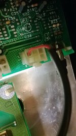
WP_20140127_006.jpg
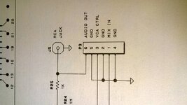
this connector here doesn't tie up with the manual, have a look bellow.
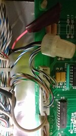
WP_20140127_009.jpg
I noticed there is a wire broken off that you can just see in the pvc covering that should go back to the main board.

So...I followed the black loom and it ends up at the main sound board as it should, but the red wire that I believe should be terminated at the connector block, is just wrapped in insulation tape, great. also, the black wire missing from the other end is here, and that's terminated, not that there is any point when the other end goes no where.
WP_20140127_005.jpg

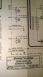
and looking at the wiring diagram for that connector, it appears the red wire should be terminated in pin 9.

WP_20140127_008.jpg
So...im thinking reconnect these and see if that fixes anything, however, why was this work done in the first place, so im hesitant to just sort it out by the diagrams.

Would there by any reason for doing this? except someone just being a total spaz? Judging by the mess of some bits on the pin that people have done, it doesn't surprise me if im honest.lol.
 
That's the right connector just missing wires lol. From the diagram looks like there should be a wire on each pin. Welcome to my world you should see the wiring on my project lol
 
yeah, i dont understand how someone can possibly thing 'hey, there are wires in this connector from the manufacturer, lets dick about with them and cut and remove them!'

Trouble is Rudedogg, this was SUPPOSED to be a fully working machine, so far i have had to replace 2 transistors, variety of bulbs and fuses, replace melted coils and rebuild a flipper. I wouldnt have minded but it was bought as a birthday present for me and i havent yet played a single game with everything working. I would love to get hold of the guy who sold it her and tell him what i think of him.

Anyhow...

I can sort the 3 GNDs on P3 because thats the black wire thats been cut off, so i can just put in a new wire and loop over to the other 2 GNDs i assume.

The other end on A6P2 i can re connect the red wire that i assume is the audio output on pin 9 which comes from pin 1 mix in on connector P3.

That just leaves P3 connector pin 6 and pin 3, the audio out and VCA CTRL, which i have no idea what to do with those. There are no loose wires profesionally wrapped in tape that i can see.
 
yeah, i dont understand how someone can possibly thing 'hey, there are wires in this connector from the manufacturer, lets dick about with them and cut and remove them!'

It's possible that something wasn't working correctly (loud screech or annoying buzz) so they disconnected that wire rather than sort the cause of the fault.

I can sort the 3 GNDs on P3 because thats the black wire thats been cut off, so i can just put in a new wire and loop over to the other 2 GNDs i assume.

The other end on A6P2 i can re connect the red wire that i assume is the audio output on pin 9 which comes from pin 1 mix in on connector P3.

Black wire goes to either pin 5, 2 or 4 on P3 and I would reconnect it to help keep the earths the same (but bear in mind that it may have been disconnected to stop annoying noise).

I'd leave the 3 (well 4) GNDs on P3 (but buzz them to make sure they're ok). That could have been done in the factory, who knows...

Yes reconnect the red wire to pin 9.

That just leaves P3 connector pin 6 and pin 3, the audio out and VCA CTRL, which i have no idea what to do with those. There are no loose wires profesionally wrapped in tape that i can see.

They're not connected, extra/redundant capability possibly needed for another game of the same era. Your game is using the J5 RCA jack by the looks of things which pin 6 is feeding anyway.
 
What Peter said. You are reading the PCb schematic , that doesn't mean anything is going to connect to it. Take a look at ipdb and you'll see a picture the same as you are describing. The ground is connected at one end for shielding the audio cable. A connection at the other end is unnecessary as it can introduce a ground loop and unwanted noise.
 
Thanks for the input guys, really appreciated.

Pinballmania - just looked on ipdb and you are correct yes, so i think i will reconnect the red wire only, and see what the actual fault is.

Im expecting some messed up sound but atleast that may help progress how to go about fixing the sound issue.
 
Put a new molex on the detached wire and put it back in the connector, powered up the machine and got a horrible squealing tone over the sound I originally had. So im guessing it was a quick fix by someone and the board needs repair work. Ill go over the board and buz everything out this week, then I suppose if I cant find anything, it needs to be sent away so the chips can be tested?
 
Put a new molex on the detached wire and put it back in the connector, powered up the machine and got a horrible squealing tone over the sound I originally had. So im guessing it was a quick fix by someone and the board needs repair work. Ill go over the board and buz everything out this week, then I suppose if I cant find anything, it needs to be sent away so the chips can be tested?

Yep.
 
OK guys, repair it is. I have been over both boards with a fine tooth comb (well...multimeter to be precise) and cannot find a single thing wrong with either board,tested all the connections, traces and caps, so, it must be a chip gone south and since the aux sound board seems to be working fine when in the game, im going to need to get the main sound board repaired by someone.

Is there anyone on here that does that? Also how much am i looking at cost wise?

cheers
 
UPDATE:

OK guys, so, after trying quite a few places for repair, noone seemed to want to take it on due to the apparant nature of the system3 sound boards being notoriously awquard to fix. So i started looking into a replacement, i found a chap who would reluctantly sell me one in the UK for £75 with the trade of my faulty one, which i was happy with, then i happened to meet a guy who offered to take a look at it for me, after having the board for a few days, he brought it back to me to test. He said some 'clown' (exacly how he put it) had replaced a chip, made a hash of it and had connected it up totally wrong after knackering trace on the board and putting in wrongly linked bridging wires between 2 chips which you can see in my board photos.

So maybe a glimmer of hope, he says it should work unless the chip that was replaced has been fried by the last person who attemped to change it. If it doesnt work, he says he will have to test other chips and see if he can find the faulty one.
 
Back
Top Bottom