What's new
Pinball info

Register a free account today to become a member! Once signed in, you'll be able to participate on this site by adding your own topics and posts, as well as connect with other members through your own private inbox!

Flasher problems scared stiff

Steve Arnold

Registered
Joined
Jul 26, 2011
Messages
372
Hi guys, I don’t seem to have any flashers working on my scared stiff pinball. The red globe flashers stopped working a few months back but today I have no flashers at all.
Checked all the fuses and all are good.
Where can I start to look for problems?

Thanks
STEVE
 
Transistors, I’ve replaced a few to cure this. Quite easy job all considered but not plug and play.
 
The globe red flashers stopped months ago. Now I get no flashers at all in test mode or game play. The20v led lift but dims when each flasher should be on. Just seems odd that none are working.
Where can I look over than replacing all the transistors for them. Also what transistors would I be looking for?

Thanks
Steve
 
I have made sure the interlock switches were closed as if the door was shut but still nothing.
 
Sounds like a connector issue or a fuse to me. Very unusual for a load of trannies to get fried at once.

If the fuse is ok, what is common to every flasher in the game ? They are probably all on the same connector.

I have a scared stiff. This snap is taken from the flasher test 20190317_150128.jpg

Every flasher seems to have this red white wire as a common element. I wonder whether you have a break in continuity on this wire/ or a bad board pin, or a bad connector.

Look in the manual to see where this red and white wire terminates. I reckon that connector could be your problem
 
Steve - if you want to pop over to me in brum I would gladly take a look. I have no idea where you are. Sounds like something simple/daft

It is worth going by the transformer and disconnecting the door switch. It is just the case of unplugging two molex.
 
Had this problem on a WPC game, I think it was the bridge rectifier and/or the capacitor. The clue is the led dimming or going out when the flasher is activated.
 
  • Like
Reactions: DRD
This happened on my no fear, shotgunned the BR and Cap, but start simple... fuse, wiring etc
 
Hi, sorry to resurrect an old thread of mine. Today a friend came over and we emt hours trying to fix this issue as I never got it sorted and work life got in the way.
today we checked fuses, wiring, connectors c10 cap and replaced it. Still get the test led dim when flashers try to fire. Bulb will glow reasonably bright first flash then dimmer each time in test mode. Only thing we have not done if replace the big diodes D16-19 I think it was. Voltage at the test point for 20v is like 15v and slowly drops.

Any ideas where to look next? Could it be the diodes? Seems like I’m not getting enough power to the test point. A long shot but do the transformers in the bottom of the cab go bad very often.

Thanks for any help you guys can give me.

Thanks
Steve
 
Steve, you've also reminded me that it possible that your problem may be caused by a number of blown flasher bulbs. You need to check each and every flasher bulb, above and under the playfield and in the backbox. Test in a known working game using the flasher test. Replace all blown bulbs then check to see if you have working flashers. SS manual page 2-47 shows the location of playfield flashers.

If that doesn't work then I'd get Phil in to sort it.
 
Thanks for the reply.
I have had a lot of it tested and have ordered some new diodes for the main board.
If that doesn’t work I might have to call someone in I guess.
Once I get them replaced I will report back.

Thanks
Steve
 
Ok another update.
I have checked all the flasher bulbs and they are ok. Replaced the big cap on the wpc95 board and diodes d15-d18 but still no change.
he flashers will flash in test mode, reasonably bright first flash then dim each time until after 4 flashes nothing. Not sure where else to look.
from what I remember a couple of years ago all was working fine until I tried an led in the flasher then I seem to remember when they stopped working properly. If hat was the case could I have damaged something else?
Checked wiring and seems ok, just voltages are very low on the flasher line which drops each flash. Could the transformer in the bottom of the cab be at fault?

Thanks
Steve
 
Hi Steve
you say you get 15V at the test point, test again this 20V test point but with J133 and J134 unplugged
what we're doing is isolating ALL the flash-lamps on the playfield and backbox
Cheers Bob
 
Thanks Bob. Tested with 133/134 connected and I get 8v dropping to 5v in attract mode. Same in test mode.
With j133/134 disconnected I get 15v in test mode.
Does that help?

Kenny, I wish I had never tried just the one led in the flasher.
I have leds in the backbox 44 which I think should be fine but none one the playfield or flashers.

Thanks
Steve
 
N no one led 104 20v test point is 2v in attract mode and doesn’t even light the led.

Any pointers?
I’m off work now for 10 days with covid so have some time one my hands to try and solve this issue!!!!!
Thanks
 
Here is a video in test mode. The led dims each time the flasher tries to light.
 

Attachments

  • IMG_1695.MOV
    31.2 MB
When you replaced the capacitor did you check you had good continuity between the diodes and the capacitor? It’s hard to make good connection if the tracks run on the component side. With your meter measure the voltage again but on an AC setting. If you get a reading in Volts rather than milivolts then the capacitor is probably not connected. Place jumper wires in place of the broken links.
 
Sorry to be thick, but what role do the capacitors play in the flasher circuits pls ?

I have 4 flashers on a single circuit on my Space Station and there is not enough power to make them really pop. Removing one flasher bulb makes the remaining ones far brighter.
 
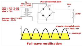
In simple terms. When the AC voltage is converted to DC by the bridge rectifiers, the negative part of the AC voltage is flipped over to positve voltage as in the picture below. The peak voltage is 18v, but the average voltage is just 11.4v dc.

Adding a capacitor provides a reserve of energy that smooths the alternating voltage and depending on its size increases the average dc voltage somewhere close to peak voltage.

Without the capacitor, if the lamp if pulsed on, the voltage appllied could be anywhere between 0V and 18V. With the capacitor in place you have a constant DC voltage available regardless of when the lamp is pulsed.
diode23.png
 
also check your bridge. You'll see its made of four interconnected diodes. If a single one fails, then you loose every other cycle of voltage. The capacitor will do its best, but will not have enough reserves to keep the voltage up.
 
Thanks for the informative description Andy pinball mania.
i have a good friend coming over hopefully next week who is an electronics engineer so will get him to take a look a s show him the thread you guys have been kind enough to advise me on.
once he has been I will update he thread.

thanks
steve
 
Yes I may end up doing this. Just need to make sure it’s not other problems on the pinball first.
Thanks
Steve
 
Back
Top Bottom