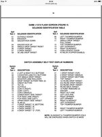
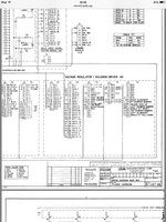
I have picked up a flash gordon project,the mpu had battery corrosion,but I had an altek board so was able to swap it out and fire it up,the game plays but with a couple of wierd issues.The right spinner when hit also fires the right slingshot,plus the game will only give you 2 balls then end despite having the dips set for 3 or 5 balls(if however you press the coin door test switch and cycle through the tests to the end,it will give you 5 balls,but then when you turn the mains off and back on it reverts to 2 balls).any ideas why?,ive checked the switches for shorts on the spinner and slingshot but they seem fine?
Pinball info
You are using an out of date browser. It may not display this or other websites correctly.
You should upgrade or use an alternative browser.
You should upgrade or use an alternative browser.
FLASH GORDON gremlins
- Thread starter stevebm1
- Start date
Have you reset the altek board ?
Have you then put the code in for Flash Gordon ?
Have you then put the code in for Flash Gordon ?
Could this be a switch matrix problem caused by a shorted diode somewhere? My thinking is that the Right Spinner and Sling are on the same strobe column, so if there are any closed switches in the same return rows it may help you identify which switch could have the duff diode to cause the Sling to fire.
ok bit of an update,solved the 2 ball problem,there was an old 50p piece wedged in the coin mech causing the switch to be stuck on,that solved that problem.Ive just noticed that when in solenoid test both the left and right pop bumpers fire,when only the right one should,could that be causing the slingshot problem?
Cut one leg of the cap on the right spinner ,and see what it's does ,could be a faulty cap or diode on the switch ?
Ok !
Cut the leg off one side of the diode .
This will make the switch not to work !!
Play a game and see if that sorts the problem .
Cut the leg off one side of the diode .
This will make the switch not to work !!
Play a game and see if that sorts the problem .
spinner
ok !
resolder diode back on ,that switch is ok!
just thinking the tip 102 work on 2 coils . i wonder just check the diodes on the driver board ?
and the tips ?
resolder diode back on ,that switch is ok!
just thinking the tip 102 work on 2 coils . i wonder just check the diodes on the driver board ?
and the tips ?
ok swapped the solenoid driver board over with the one from vector and it did exactly the same,then I noticed someone had soldered one of the diodes on a rollover switch wrong,I snipped this off and it solved the spinner/slingshot issue,hasn't solved the left pop bumper firing,when the right does in solonoid test mode though
well spotted on the rollover switch 
right so we know now that the mpu is ok and the driver board ok ,
so this has to mine that the fault is on the playfield
cheak the wires on the coils are correct + check the diode

right so we know now that the mpu is ok and the driver board ok ,
so this has to mine that the fault is on the playfield
cheak the wires on the coils are correct + check the diode
ok new solder station arrived today,so had some more time to look at it,I changed diodes on the pop bumpers but it's still the same, the right one fires by itself in the game,but not during test mode- the left one goes with it,think I may just have to live with it,the games playable,if I hadn't have been running the solenoid test,I probably wouldn't even have noticed
what happens in switch test !
in switch test it says switch 03 is stuck on,thats the single drop target at the end of the shooter lane,it is supposed to be down to start a ball,and comes up afterwards once the ball hits a rollover on the shooter lane exit,it does this,so why it's saying 03 is stuck on is a mystery,if you raise the target by hand it passes the switch test
03 is not suck on its closed and when you lift the target its now "open"
so thats a good sign
so in switch test , test the pop bumbers and note the number which appears on the display and cross cheak to the manual ,just to see if that switch operate that pop bumber and so on !
so thats a good sign

so in switch test , test the pop bumbers and note the number which appears on the display and cross cheak to the manual ,just to see if that switch operate that pop bumber and so on !
Hi Steve
the phantom operations of pop bumpers in games of this era is very common here is a link to a humongous
post on pinside forum. https://pinside.com/pinball/forum/topic/pop-bumper-fires-with-flipper-activity
may give you some insight on this problem
the phantom operations of pop bumpers in games of this era is very common here is a link to a humongous
post on pinside forum. https://pinside.com/pinball/forum/topic/pop-bumper-fires-with-flipper-activity
may give you some insight on this problem
thanks for the link,Ive read it through but I don't think thats my problem,in solonoid test it's number 10 that fires the right and left bumpersHi Steve
the phantom operations of pop bumpers in games of this era is very common here is a link to a humongous
post on pinside forum. https://pinside.com/pinball/forum/topic/pop-bumper-fires-with-flipper-activity
may give you some insight on this problem
in sol test = 9 is left pop bumber
10 is right pop bumber
check pin J 5 pin 11 orange / black wire ,maybe bad contection ?
switch test i think its number 39 opperates left pop bumber and 40 is the right .
what happens when pressed in test ?
There is orange / black going to the pop number ?
10 is right pop bumber
check pin J 5 pin 11 orange / black wire ,maybe bad contection ?
switch test i think its number 39 opperates left pop bumber and 40 is the right .
what happens when pressed in test ?
There is orange / black going to the pop number ?
Last edited:
So it looks like left and right wires on the coils are wrong way round !
ok ive sorted this now,someone had indeed put the wires on the wrong way round,plus they had stuck a wire with a diode going from the right to left pop bumper for some reason ,I fixed the bodge job and it's working fine now in test and in game.
 ,I fixed the bodge job and it's working fine now in test and in game.
