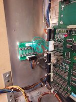
Thought this guide maybe useful to some. My black knight has just come out of storage after a ten year sleep.....!
It's completely dead. The power supply needs a rebuild and the existing rectifiers are the originals, so past their best by now. Also this machine was tombstoned way before inkochnito had invented his bridge board. So this game had the old fashioned anti-combustion mod..which you can see in the picture below...so would be good to remove this also. (Effective , but a bit of a hack!)
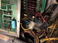
Here's a picture of the pcb, with the voltages marked up.......
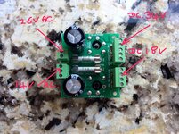
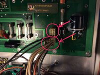
So here goes..first we need to remove the two existing bridge rectifiers and the large blue capacitor. (Circled).
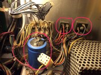
Just cut all the wires off at the components. Also unplug the two connectors from the power supply pcb, as circled below......
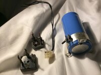
Once all are removed you will be left with this, also a short black cable and a short purple cable will need removing as they previously connected to the old capacitor and one of the old bridge rectifiers. These easily just pull out of the existing cable ties. Here's what needs removing, the connector with the two black wires will be reused, so do not chuck that!
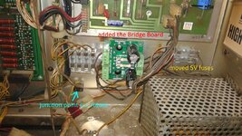
Now we need to mount the new pcb in the backbox. Easiest thing to do is to move the fuse block to the left about 40mm , then you have enough room to mount inkochnitos board, use the old screws from the old bridge rectifiers.also you need to add an additional earth connection on some early versions, ours is an early one so I made up an earth strap (circled.you could reuse the black cable you removed earlier if it's in good condition)...like this.....
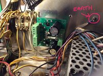
Now it is time to connect up all the cables to the new pcb. All the plugs are different sizes so no chance of connecting them up incorrectly to the new pcb. First the 34v dc cables, they go on the five pin connector on the new pcb.these are the blue and orange ones connected together at one of the old bridge rectifiers, and also the larger block removed from the power pcb. Also join in the new earth here if required.........
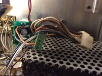
Next we will do the 18v dc connections. This is the 4 pin connection on the inkochnito pcb. These cables are the two black ground cables from the power supply pcb and the purple cable......
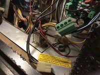
Next 14vac connections. This is the 3 pin connector on the inkochnito pcb. These are the two blue wires cut from the other old rectifier from the transformer....like this.......
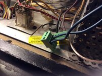
Finally this leaves the two red wires that are your 26vac connections......into the two pin inkochnito connector....
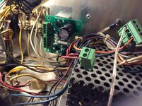
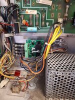
Now is the time to plug in all the connectors to the new inkochnito pcb. These can only fit in one place in one way so no chance of incorrect connections......then turn on the machine and you should have power and two leds lit on the new pcb. The machine is ready to test/ play...in my case test as it's not powered up for a decade!!!........
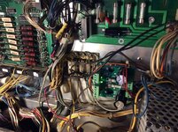
JOB DONE............WATCH THIS SPACE AS TO HOW MANY FAULTS THE GAME HAS..............
It's completely dead. The power supply needs a rebuild and the existing rectifiers are the originals, so past their best by now. Also this machine was tombstoned way before inkochnito had invented his bridge board. So this game had the old fashioned anti-combustion mod..which you can see in the picture below...so would be good to remove this also. (Effective , but a bit of a hack!)

Here's a picture of the pcb, with the voltages marked up.......

So here goes..first we need to remove the two existing bridge rectifiers and the large blue capacitor. (Circled).

Just cut all the wires off at the components. Also unplug the two connectors from the power supply pcb, as circled below......

Once all are removed you will be left with this, also a short black cable and a short purple cable will need removing as they previously connected to the old capacitor and one of the old bridge rectifiers. These easily just pull out of the existing cable ties. Here's what needs removing, the connector with the two black wires will be reused, so do not chuck that!

Now we need to mount the new pcb in the backbox. Easiest thing to do is to move the fuse block to the left about 40mm , then you have enough room to mount inkochnitos board, use the old screws from the old bridge rectifiers.also you need to add an additional earth connection on some early versions, ours is an early one so I made up an earth strap (circled.you could reuse the black cable you removed earlier if it's in good condition)...like this.....

Now it is time to connect up all the cables to the new pcb. All the plugs are different sizes so no chance of connecting them up incorrectly to the new pcb. First the 34v dc cables, they go on the five pin connector on the new pcb.these are the blue and orange ones connected together at one of the old bridge rectifiers, and also the larger block removed from the power pcb. Also join in the new earth here if required.........

Next we will do the 18v dc connections. This is the 4 pin connection on the inkochnito pcb. These cables are the two black ground cables from the power supply pcb and the purple cable......

Next 14vac connections. This is the 3 pin connector on the inkochnito pcb. These are the two blue wires cut from the other old rectifier from the transformer....like this.......

Finally this leaves the two red wires that are your 26vac connections......into the two pin inkochnito connector....

Now is the time to plug in all the connectors to the new inkochnito pcb. These can only fit in one place in one way so no chance of incorrect connections......then turn on the machine and you should have power and two leds lit on the new pcb. The machine is ready to test/ play...in my case test as it's not powered up for a decade!!!........

JOB DONE............WATCH THIS SPACE AS TO HOW MANY FAULTS THE GAME HAS..............
Last edited:

