Before i go on off one thankyou to @Zaccaria Keith for his neon removal guide - thanks mate.
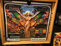
Okay, so i bought a new back glass from Coos in da Nederlands, thank you pleash. And very good it looks too!
But... I ain't no fool! If I swapped out the back glass and left the neon in, most likely after a few shows i will have a couple of holes in my spinky art work in front of the hot, UV emitting tube ends... So the neon has got to go,
Another but... The neon works fine and if i ever move the table on, i want the transformer and neon to go with it so that it is all together. Neon very fragile, me clumsy kunt. So i need to be able to keep it safe...
Que storage thing, that will hence forth be called 'Fred', Fred the Farfalla Neon Storage Vessel.
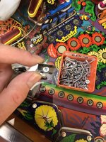
Before i get to that a couple of shots of the tube ends. I had to cut back the heat shrink with a dremel
and a craft knife (such fun) to expose the connections between the tube ends and the HT leads - conductors just twisted together.


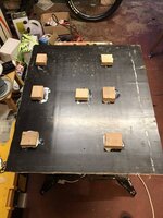
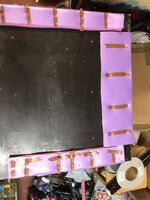
Fred was two shets of 1" ply, cut to the area of the tube: -


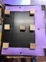
I then PVAd a couple squares of ply to act as spacers and fixings to create a sandwich. Note it was not deep enough so i later had to stick another bunch of sqaures on top. When the glue dried a couple of screws in the corners of the blocks to ensure a good fixing to the board.
Now i need a bit of padding.
Que 9issed of Mrs and the missing Yoga mat...

A few staples later and we have a nice shock absorber. Then lay the tube, carefully, over the top to get the location of the three sprung suspension screws.

Now cut out location of the three screws:-


Now i need to do the same width other side of the sandwich. Note i needed to fold over the padding to create a thicker layer so it slightly makes contact with the tube, note the insulation tape - this stops the staples ripping through.

A bit of red paint (was small blobs) on the four blocks then lay the other half of the sandwich on top so the paint marks where i need to drill some pilot holes for the screws to secure the other side.

Screw them both togethoer and I have a nice Fred Vesel. I can now start wok on the LED bit...
The sandwich on its edge.

Some fetching straps to secure the cables of the HT transformer (screwed to the front) - shocker in disguise...

Next part due soon, i bet you just can't take the tension, the high tension... see what i did there, HT...
Okay, so i bought a new back glass from Coos in da Nederlands, thank you pleash. And very good it looks too!
But... I ain't no fool! If I swapped out the back glass and left the neon in, most likely after a few shows i will have a couple of holes in my spinky art work in front of the hot, UV emitting tube ends... So the neon has got to go,
Another but... The neon works fine and if i ever move the table on, i want the transformer and neon to go with it so that it is all together. Neon very fragile, me clumsy kunt. So i need to be able to keep it safe...
Que storage thing, that will hence forth be called 'Fred', Fred the Farfalla Neon Storage Vessel.
Before i get to that a couple of shots of the tube ends. I had to cut back the heat shrink with a dremel
and a craft knife (such fun) to expose the connections between the tube ends and the HT leads - conductors just twisted together.
Fred was two shets of 1" ply, cut to the area of the tube: -
I then PVAd a couple squares of ply to act as spacers and fixings to create a sandwich. Note it was not deep enough so i later had to stick another bunch of sqaures on top. When the glue dried a couple of screws in the corners of the blocks to ensure a good fixing to the board.
Now i need a bit of padding.
Que 9issed of Mrs and the missing Yoga mat...
A few staples later and we have a nice shock absorber. Then lay the tube, carefully, over the top to get the location of the three sprung suspension screws.
Now cut out location of the three screws:-
Now i need to do the same width other side of the sandwich. Note i needed to fold over the padding to create a thicker layer so it slightly makes contact with the tube, note the insulation tape - this stops the staples ripping through.
A bit of red paint (was small blobs) on the four blocks then lay the other half of the sandwich on top so the paint marks where i need to drill some pilot holes for the screws to secure the other side.
Screw them both togethoer and I have a nice Fred Vesel. I can now start wok on the LED bit...
The sandwich on its edge.
Some fetching straps to secure the cables of the HT transformer (screwed to the front) - shocker in disguise...
Next part due soon, i bet you just can't take the tension, the high tension... see what i did there, HT...
Attachments
Last edited: