What's new
Pinball info

Register a free account today to become a member! Once signed in, you'll be able to participate on this site by adding your own topics and posts, as well as connect with other members through your own private inbox!

DW mini PF troubleshooting - need help identifying opto components please

Fubar

Site Supporter
Joined
Feb 5, 2020
Messages
1,688
Location
Cambridge, UK
Alias
Thomas
So we have a DW at the office, and the 5-bank opto targets in the middle level of the MPF weren't working properly: only 2 of them registered.

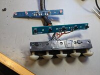
James came over to service the game and declared the PCBs beyond repair, so I got replacement opto tx/rx PCBs from Marco spec.

Now I've installed them, nothing works. It's like the optos aren't getting any power or something. In switch test, they all show as off (open). Checked all the solder joints again and they're solid. Phone camera doesn't seem to pick anything up but I'm not sure it would (new phone, never tried).

Interestingly the game now always spits out the 2nd locked ball, presumably because it can tell something is wrong.

My question is: how do I go about troubleshooting this issue? I'm guessing powering the opto PCBs on the bench? We have access to a range of hardware here, but what I don't have is much time and this thing is already a right pain just to get out of the game!

Any tips & pointers much appreciated - thanks!
 
Check connections!
Make sure you used the correct loom to the correct pcb.
Also wires can break in the loom.
I used to have some cable used in robotics from some old Land Rover production line machines but sadly all gone now.
I would check continuity of all the cables.

If you are really stuck I cover your area now and again!
 
OK so finally got some time to work on this... It turns out that the new replacement boards from marcospec don't work!

We tried mixing & matching the old & new tx/rx boards, in switch test and also measuring the DC voltage at the opto receiver output.

The conclusion was that the receivers on the new board are out of spec. They only emit 4.5V-5V, and the voltage drop when the beam is interrupted is minimal (0.1V or less in some cases). In comparison, the original board (which only has a couple working receivers) puts out VCC (about 15V although schematic says 12), down to 0V when interrupted. Using either old or new emitter board yields the same result.

So our next step is to source the opto receiver components and replace them on the PCB. (Should've done it from the start!)

Does anyone know part numbers for these please? A farnell/mouser/etc. link would be ideal. Thanks!

Edit: I see AndyN carries opto emitter/receiver parts which might be compatible?
 
Last edited:
Yep got plenty of these. How many do you need? (Lucky actually because the part was on 6 month back order with mouser, but my shipment came in in november i think!)
Great, thanks! We need 3x opto receiver parts please. Assuming they're cheap maybe we should get a spare tx/rx pair too...
 
Great, thanks! We need 3x opto receiver parts please. Assuming they're cheap maybe we should get a spare tx/rx pair too...
Just replace all 5 both sides if you have it apart and have some spares to for future
 
Ok well, this is getting a bit baffling now...

Got spare parts from Jim, replaced all the receivers - still no luck. The only receivers which work are 2 alternate ones on the old board labelled TIL81.

Measuring the voltage between the opto receiver output and GND, in the working case I get 15VDC (=VCC) at rest (normally closed), and 0V when the beam is interrupted. With the brand new receivers from Jim it measures 8V and 7.9V respectively! With the ones from marcospec it's about 5V/4.9V (but quite inconsistent between components). These are all measured using the same emitters.

Attached a pic where you can see the new board in the front, and the old board with the only 2 working receivers being the stubby grey ones.

Think I'm just going to leave the game like this as I've spent way too much time on this problem already, and the software compensates for the 3 non-working switches anyway...
 

Attachments

  • PXL_20230120_123437007.jpg
    PXL_20230120_123437007.jpg
    171.3 KB · Views: 5
Back
Top Bottom