What's new
Pinball info

Register a free account today to become a member! Once signed in, you'll be able to participate on this site by adding your own topics and posts, as well as connect with other members through your own private inbox!

Diode help - Reading Schematics

cmrl9

Site Supporter
5Years
Joined
Apr 16, 2020
Messages
2,727
Location
Belfast
So having been caught out twice by diodes, the first time not knowing what the hell they where or that they even existed and the second from having a little knowledge but still not checking the manual, I'm still a little confussed and would appreciate some help please:

1) What exacty does a diode on a coil do. My understanding is to prevent the flow of electricty back down the wrong direction. Almost like a plug/stopper, and preventing the electrictiy hitting the board the wrong way

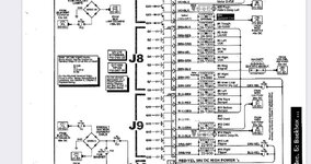
2) from the schematic diagram below (Taken from the LOTR manual):
Diode.JPG

If we take the right flipper at the bottom does the diagram mean:

Orange-violet coloured wire soldered to coil lug that is on the end of the diode without the banding. In the right flipper photo example below the wire at the bottom:
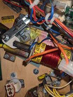
PXL_20211214_151259928(1).jpg

Diode banding at the top above BLue wire
 
and the text in white in between the coil power type:

for example "24-940" being whats written on the coil

I'm guess this is correct, but learn't not to assume.
 
Correct, the band corresponds to the line in the diode symbol in the diagram the wires are on correctly. Can‘t comment on coil type as I have never owned a Stern, but the number in the diagram looks like a coil number. With Williams it wasn‘t uncommon to have the wrong types in the manual.
 
The text above each coil on the schematic is the physical "wire gauge" - "number of turns" which defines the total wire resistance hence power of the coil.

Your flippers are showing as 22-900 (900 turns of 22 gauge wire), this website https://www.flippers.com/coil-resistance.html tells me that would measure 3.4 Ohm and the Stern part number is 090-5020-20T. (As mentioned above manuals can be wrong!)

I find this website useful to understand the basics of components https://www.electronics-tutorials.ws/diode/diode_1.html
and Clays guide more pinball specific http://www.pinrepair.com/begin/#howdmm
 
So having been caught out twice by diodes, the first time not knowing what the hell they where or that they even existed and the second from having a little knowledge but still not checking the manual, I'm still a little confussed and would appreciate some help please:

1) What exacty does a diode on a coil do. My understanding is to prevent the flow of electricty back down the wrong direction. Almost like a plug/stopper, and preventing the electrictiy hitting the board the wrong way

Yes a diode prevents damage to the circuit when the power is turned off to the coil by allowing the power to flow through the diode instead of back into the circuit. There is a lot of different names for them such as A flyback diode, snubber diode or free wheeling diode and many other names.

There are a number of decent descriptions on various websites with examples if you want to learn in more details how it works. A very simplistic description is that a coil generates a magnetic field and when you turn it off, that energy has to go somewhere, so the diode provides a short circuit path to dissipate that energy.
 
The diode on a coil is there to stop Back/Reverse EMF (Electro Magnetic Field) which will destroy the driving mosfet/transistor as diodes only allow current to flow in 1 direction.

A coil is an inductive load which generates an EMF when turned on. When it is switched off the EMF collapses and would run backwards, something that the driving parts are not designed to withstand. Therefore the diode stops this being a problem.

Coil diodes are also not always on coils directly, sometimes they are on the driver board.

It is always necessary to check the coil diode is good when repairing a bad coil/blown driver etc otherwise you could end up chasing your tail.
 
To add to the EMF bit: when the coil is switched off, the energy in the field collapses instantly and creates a voltage spike which is hundreds of volts but has very little current, enough to fry the junctions in the driver transistors over time though. So you „charge“ up the coil with low voltage over a longer time and get all the energy back out as a high voltage pulse on switch off. Same principle as the ignition coil in a car. The good thing is that the polarity of the voltage spike is reversed to how you charged it - this means that the diode (being a one way valve for current) isn‘t conducting when you switch the coil on but is shortcutting the spike on switch off.
 
Correct, the band corresponds to the line in the diode symbol in the diagram the wires are on correctly. Can‘t comment on coil type as I have never owned a Stern, but the number in the diagram looks like a coil number. With Williams it wasn‘t uncommon to have the wrong types in the manual.
Thanks so not totally stupid, except for being totaly stupid for not checking the manual first and rechecking all my work before turning the machine on. Thats very helpful.

When your not 100% sure you start to question whether you have read it right and i'm learning as I go mainly from help from this forum.
 
The text above each coil on the schematic is the physical "wire gauge" - "number of turns" which defines the total wire resistance hence power of the coil.

Your flippers are showing as 22-900 (900 turns of 22 gauge wire), this website https://www.flippers.com/coil-resistance.html tells me that would measure 3.4 Ohm and the Stern part number is 090-5020-20T. (As mentioned above manuals can be wrong!)

I find this website useful to understand the basics of components https://www.electronics-tutorials.ws/diode/diode_1.html
and Clays guide more pinball specific http://www.pinrepair.com/begin/#howdmm
Thats very helpful information, I take a read of that over the christmas break.
Personally I find answer from helpful people easier to understand, some of the online manual, help gets a little confusing. Some of the are written that you have a basic/fundumental understanding of electronic components. Unfortunetly I don't! Before a pinball machine the closest I got to a circuit board was touch the equipment that perhaps a circuit board contained *lol*
 
Yes a diode prevents damage to the circuit when the power is turned off to the coil by allowing the power to flow through the diode instead of back into the circuit. There is a lot of different names for them such as A flyback diode, snubber diode or free wheeling diode and many other names.

There are a number of decent descriptions on various websites with examples if you want to learn in more details how it works. A very simplistic description is that a coil generates a magnetic field and when you turn it off, that energy has to go somewhere, so the diode provides a short circuit path to dissipate that energy.
Thank you fantastic answer, that explains alot from a few of the problems I've had on both STTNG and LOTR.
 
The diode on a coil is there to stop Back/Reverse EMF (Electro Magnetic Field) which will destroy the driving mosfet/transistor as diodes only allow current to flow in 1 direction.

A coil is an inductive load which generates an EMF when turned on. When it is switched off the EMF collapses and would run backwards, something that the driving parts are not designed to withstand. Therefore the diode stops this being a problem.

Coil diodes are also not always on coils directly, sometimes they are on the driver board.

It is always necessary to check the coil diode is good when repairing a bad coil/blown driver etc otherwise you could end up chasing your tail.
Thanks, another fantastic explanation, very helpful, again explains a lot based on the problems I’ve had.
 
To add to the EMF bit: when the coil is switched off, the energy in the field collapses instantly and creates a voltage spike which is hundreds of volts but has very little current, enough to fry the junctions in the driver transistors over time though. So you „charge“ up the coil with low voltage over a longer time and get all the energy back out as a high voltage pulse on switch off. Same principle as the ignition coil in a car. The good thing is that the polarity of the voltage spike is reversed to how you charged it - this means that the diode (being a one way valve for current) isn‘t conducting when you switch the coil on but is shortcutting the spike on switch off.
Thanks, thats interesting and useful. It's becoming so much clearer why I've damaged boards.
 
Back
Top Bottom