What's new
Pinball info

Register a free account today to become a member! Once signed in, you'll be able to participate on this site by adding your own topics and posts, as well as connect with other members through your own private inbox!

Clicking relay on AS-2518-22 Solenoid board

Andrew65

Registered
Joined
Sep 22, 2016
Messages
23
Location
Horsham, West Sussex
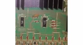
The relay on my AS-2518-22 Solenoid Driver board has started intermittently clicking (on Lost World). Sometimes it is effecting the flippers (on/off/on) and it is milliseconds interruption of supply as I believe that this relay switches the 48v for the flippers. Other times it doesnt seem to effect the flippers (possibly too quick).

This part of the circuit is only activated with a game present to play so only clicks during game play.

Has anyone had this problem before and what was the cause. From the circuit it could be either the capacitor, transistor, or the U4 (CA3081 Transistor array). The diode is fine. Not too much in that part of the circuit but not cheap and easy parts to find to just swap out and with limited test equipment not so simple to catch an intermittant fault.

Any suggestions to speed up the identification of the fault would be appreciated.

Cheers,
Andrew
 
To help t/shoot the flipper relay K1 is tested during the Solenoid test cycle. It might be worth seeing if that cycles through ok.
 
To help t/shoot the flipper relay K1 is tested during the Solenoid test cycle. It might be worth seeing if that cycles through ok.

All solenoids click through OK during the solenoid test. Game plays and flippers work 99.9% of the time. Just sometimes they click off and then back on at the same time the relay clicks. Other times the relay will click and flippers do not go off/on. Definitely seems a driver board problem rather than the Solenoid on the flippers.
 
Often a bad connector. Try flexing them and see if it induces clicking.

Been there and tried that. Doesnt seem to make a difference. Cleaned pins also. Reflowed solder in the circuit too. Sometimes it is worse than others. generally seems worse when hot which seems to point to dry solder joint or failing part but is also an issue when first started up. Silly idea to have the power supply and extra heat in the back box imho.
 
Just sometimes they click off and then back on at the same time the relay clicks.

I think the flipper relay (K1) remains continuously enabled while a game is in progress. If you're hearing it clicking during the game then this would affect the flippers. I'd be investigating the signal side before K1, so this is driven from MPU A4 J4-7 to the HV Reg A3 J4-8. Are those the connectors/headers you're investigating per pbm and moonrakers suggestions above?
 
Thanks all for your suggestions. I think I may have tracked it down now. Tried all the re-seating and wire wiggling etc with no positive outcome. Normally the first thing I try on these old games.

The relay is held open by U4 and Q15. As this was intermittent It was either the message from the MPU board, which checked out OK, or the circuit on the solenoid board. So it was down to either of U4 chip, Q15 tranny, flaky diode, or the C11 Cap. Diode checked out OK but replaced just in case but no change. As the cap was the cheapest of the rest I replaced the cap and now it seems stable. Probably not holding its charge to keep Q15 switched.

So a few pence to fix and a happy camper.
 
Nice one that Cap could be nearly 40 years old. Btw do you mean U11 on MPU A4 which drives A3 Q15? (I'm trying to learn these schematics to maintain my own early Ballys).
 
Nice one that Cap could be nearly 40 years old. Btw do you mean U11 on MPU A4 which drives A3 Q15? (I'm trying to learn these schematics to maintain my own early Ballys).

No I mean U4 on the solenoid board. Q15 is driven by U4 which in turn was driven from the MPU board. The switching network you see on the circuit diagram just before Q15 is a switching IC (CA3081 type) they named U4.
 
No I mean U4 on the solenoid board. Q15 is driven by U4 which in turn was driven from the MPU board. The switching network you see on the circuit diagram just before Q15 is a switching IC (CA3081 type) they named U4.
I had to replace the CA3081 on my Vector because the relay was permanently energised.
I had to source one from Canada !
 
Try Best of Pinball in Germany . they have the SG3081N which I think is a substitute.
When I looked into it I think the newer ones are borderline on the voltages they can handle. That's why I sourced an original.
 
When I looked into it I think the newer ones are borderline on the voltages they can handle. That's why I sourced an original.

All spec sheets I can find seem to be the same on voltages & current handling. CA3081 should be the same as NTE916, SG3081N, ULN2081A. Unfortunately not too many sources in the UK for any of them. Maybe a sideline business idea?
 
All spec sheets I can find seem to be the same on voltages & current handling. CA3081 should be the same as NTE916, SG3081N, ULN2081A. Unfortunately not too many sources in the UK for any of them. Maybe a sideline business idea?
It is certainly a tricky part to source. Might be worth removing them from any knackered Solenoid Driver Boards if anyone has any.
 
Hi
Normally its only one transistor that's defective in the pack. I normally cut the corresponding chip legs for the base & collector flush to the chip body. Remove the legs and clear the pcb holes then just straddle and solder a BC548 across the chip body. Here's a Flash Gordon that i did recently. Thinking about it you could do this on the underside of the board hide the re-work.
Cheers Bob
 

Attachments

  • ca3081.jpg
    ca3081.jpg
    62.8 KB · Views: 7
  • ca3081.jpg
    ca3081.jpg
    62.8 KB · Views: 7
Back
Top Bottom