Pinball info
You are using an out of date browser. It may not display this or other websites correctly.
You should upgrade or use an alternative browser.
You should upgrade or use an alternative browser.
Complete CFTBL Chase Echo | A new chase board for creech | New 50pcs 2024 run
- Thread starter stumblor
- Start date
Davey don't forget I want a set of those babies............
Davey don't forget I want a set of those babies............
There's that dam echo again.
Or these are so good they said it four times.

Okay, okay... Where do I start? I'll point form my comments so that I don't post a book as my very first post on pinballinfo;
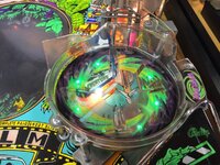
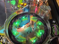
1. That has to be the nicest Creature I have ever seen.
2. Those pink and blue LEDs are fantastic. They just went onto my "purchase" list.
3. Is that a self-made PURPLE reed switch on the whirlpool bowl?
4. Another great product name! First THE RIPPLER, and now CHASE ECHO. Just a great font, and perfect placement.
5. Killer video. Well filmed (some auto zooming there), great overlay graphics, clean, clean, clean.
6. Price. Winner! Winner! 100GBP is still about $175CAD, but that's better than $235USD which is nearly $320CAD.
Tim
OP
OP
Okay, okay... Where do I start? I'll point form my comments so that I don't post a book as my very first post on pinballinfo;
1. That has to be the nicest Creature I have ever seen.
2. Those pink and blue LEDs are fantastic. They just went onto my "purchase" list.
3. Is that a self-made PURPLE reed switch on the whirlpool bowl?
4. Another great product name! First THE RIPPLER, and now CHASE ECHO. Just a great font, and perfect placement.
5. Killer video. Well filmed (some auto zooming there), great overlay graphics, clean, clean, clean.
6. Price. Winner! Winner! 100GBP is still about $175CAD, but that's better than $235USD which is nearly $320CAD.
Tim
Ahh thanks @Fifty, nice of you to say. And a big welcome to pinballinfo! For more creech related pornography, check out my shop log.
'Fraid I can't take credit for the reed switch, that's one of the pinside MRS ones attached with a purple slip tie
 smoke and mirrors!
Incidentally, the chase echo styling is based on the Space Echo, a famous tape echo from the 70s.

Hey, I'm on the list for this right? I didn't see me mentioning that anywhere. To save time, just put me on the list for all your mods.
OP
OP
Hey, I'm on the list for this right? I didn't see me mentioning that anywhere. To save time, just put me on the list for all your mods.
Yes mate you're on - the project is just held up currently while I sort out some ac/dc powering issues. Hopefully have some more news on this soon.
OP
OP
The first set of boards went out a few weeks ago, and we quickly realised there was a bit of a niggle with the board design. Because the fading of the LEDs was being achieved using pulse width modulation (a DC signal pulsing at varying high frequencies, giving the appearance of fading) all the LEDs needed to be oriented in a particular direction, otherwise they wouldn't work. Not a deal breaker, but super annoying considering that all the ramps need to be removed, the strips pulled out, tested, and then any LEDs that weren't firing turned around in the housing. Not exactly an installation plan I would call 'plug and play'.
The original boards used AC to power the strips (like all GI lighting), which is why LED direction wasn't a problem. I thought I'd have a crack at redesigning the board to handle AC dimming. Couldn't be that hard, right?
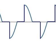
Now if you're an electrician, (or an idiot like me who researches this stuff for kicks) you'll probably know that AC dimming can be done in two different ways. They're referred to as leading edge and trailing edge dimming.
Leading edge dimming is when the AC signal is cutoff partway through it's half cycle, which lessens the overall output and dims the bulbs.

This is the easier (and cheaper) type of AC dimmer to build, and uses Triacs under the hood. As we all know by referring to the scientific theorem of Sod, easier ways always have a catastrophic gotcha that will render the design unusable. And why would this be any different? Leading edge dimming causes LEDs to flicker horribly. So out that plan goes.
That leaves us with trailing edge dimming, which is where the half cycle is only activated partway through the half cycle.

Most modern LED dimmers, the ones you buy for your fancy light switches in your disco lit pinball dungeons, will use this method. The theorem of sod explains that while this method will be perfect for LED based dimming situations, it will be about 3 times as complicated a circuit to build. That Sod - such a character!
The new circuit!

Figure 3 - Look at that horrific array of mosfets
The new circuit change is made up of..
Doesn't look like much, but this is a big breakthrough.
Still need to confirm that the fading technique I'm using results in a similar pattern effect, which will require building out the additional channels.
@replicas @Toxteth O'Grady @davro-one @Calimori @Ads Nems @Fifty
The original boards used AC to power the strips (like all GI lighting), which is why LED direction wasn't a problem. I thought I'd have a crack at redesigning the board to handle AC dimming. Couldn't be that hard, right?
Now if you're an electrician, (or an idiot like me who researches this stuff for kicks) you'll probably know that AC dimming can be done in two different ways. They're referred to as leading edge and trailing edge dimming.
Leading edge dimming is when the AC signal is cutoff partway through it's half cycle, which lessens the overall output and dims the bulbs.
This is the easier (and cheaper) type of AC dimmer to build, and uses Triacs under the hood. As we all know by referring to the scientific theorem of Sod, easier ways always have a catastrophic gotcha that will render the design unusable. And why would this be any different? Leading edge dimming causes LEDs to flicker horribly. So out that plan goes.
That leaves us with trailing edge dimming, which is where the half cycle is only activated partway through the half cycle.
Most modern LED dimmers, the ones you buy for your fancy light switches in your disco lit pinball dungeons, will use this method. The theorem of sod explains that while this method will be perfect for LED based dimming situations, it will be about 3 times as complicated a circuit to build. That Sod - such a character!
The new circuit!
Figure 3 - Look at that horrific array of mosfets
The new circuit change is made up of..
- 1 x opto isolator (used to electronically isolate two circuits, ie, AC and DC) to calculate the zero crossing
- 8 x opto isolators, to isolate the DC drive circuit from the AC mosfets
- 16 x mosfets (up from 8), one to manage each side of the AC cycle
Doesn't look like much, but this is a big breakthrough.
Still need to confirm that the fading technique I'm using results in a similar pattern effect, which will require building out the additional channels.
@replicas @Toxteth O'Grady @davro-one @Calimori @Ads Nems @Fifty
Attachments
Short but sweet video. Forward progress is better than stepping backwards or zero progress.
@stumblor, I think you would get along with my wife. She is always telling me, "You are your own worst critic".
With regards to the MOSFETS, what was the logic for using through-hole components instead of SMD?
@stumblor, I think you would get along with my wife. She is always telling me, "You are your own worst critic".
With regards to the MOSFETS, what was the logic for using through-hole components instead of SMD?
OP
OP
Short but sweet video. Forward progress is better than stepping backwards or zero progress.
@stumblor, I think you would get along with my wife. She is always telling me, "You are your own worst critic".
With regards to the MOSFETS, what was the logic for using through-hole components instead of SMD?
Only that they're a lot easier to solder!
")
OP
OP
The new AC re-design of the Chase Echo is finally, *finally*, ready. This new design addresses the issue where all ramp LEDs needed to be oriented correctly before they would work. While not a deal breaker, who wants to be flipping ramp LEDs when you could be chugging a beer and high fiving a life sized creech replica? Not you, that's not who!

The last time I saw that many mosfets I was seeing double.
The last two weeks has been spent trying to work out why everything worked fine on the bench, but not in my machine. Two nights ago at 1am it occurred to me that I'm running an Afterglow GI in my machine, so the GI wasn't going to be AC anyway. Both the Afterglow GI and LEDOCD GI convert the GI to pulsed DC. Once that had been switched back it worked fine. (An adapter solution will be available for those users with Afterglow and LEDOCD boards)
@Toxteth O'Grady on beta testing duties.
If you're a V1 user and feel a bit cheesy that your old board aint as sexy as the new board, good news! Send me your old one and I'll replace it free of charge. You still might not be a hit with ladies, but your pinball buddies will think you're a boss.
Nice catch on this. Pulsed DC. I would've probably thought of that... in about a year.
OP
OP
After numerous requests to re-run the "Chase Echo" - our replacement chase board for creech - we've decided to push ahead with a super limited 50pcs build.
Interestingly, the Chase Echo runs an early version of the "Lolly" firmware, before it was even called that. It was this code that was then ported over to the WiFi enabled ESP chip, given some RGB functionality, and is now driving all our mods. So if some of the patterns looks familiar, you'll know why!
You can sign up for that here:
https://stumblorpinball.com/products/echo
Once they're gone, they're gone!
