What's new
Pinball info

Register a free account today to become a member! Once signed in, you'll be able to participate on this site by adding your own topics and posts, as well as connect with other members through your own private inbox!

Bride of Pinbot helmet lights not working.

OK, the board on the photo is the power board, not the relay board, we're talking about that?
According to the manual, pin 3 is the key so shouldn't be present. Pin 2 should be ground into the board, this one should go back to the PDB and must have continuity to ground, otherwise the head wouldn't be turning. The loop is then connected to pin 3, but not to the board, as there is no pin in that position on the board. Now the manual may be wrong again and pin 2 and three are swapped but that doesn't matter. Measure connectivity from ground to pin 2 and 3 as well as the chase board on the black cable. The black cable is probably broken in the loop or somewhere between pin3 and the chase board. Please check if the key is indeed correct, i.e. a pin is missing on the header. If there is a pin and that carries 10V somehow, you have a broken cable and a wrong header. What confuses me is that you have 10V on the black cable at the chase board even with the plug disconnected, that must be coming from somewhere.
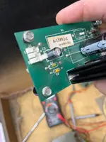
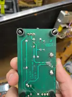
Yes sorry talking about the power motor board. The ground from the PDB is located on pin 3 and has connectivity all the way back. Pin 2 on the power board runs back to the chase board and has connectivity all the way on that one. I have 10v at pin two on the power motor board and that goes back to the chase board carrying power. I have no volts on pin three and that comes from the pbc j-117 pin 3. Looking at the schematics it looks like I should have the J-117 pin 3 black ground coming to pin 2 not pin three on the motor power board. Not the case now. It’s on pin 2. If I make that change do I put the ground on pin going to the chase board on pin 3 of the motor power board? Also I know you said earlier the pins were back wards on the chase lamp board. Based on what I see on the schematics it should be the constant on 5 not 1 and the ground should be on 4 not 2. Then the two blue. One dark and one light should be on pins 1 and 2 for the clock and date. I have been trying to watch learn and read schematics as we do this.

In the motor relay board J1 the key is pin 3.

Hope that answer the questions. Really can not thank you enough for helping me with this.
 
OK, just to make sure:
- We are looking at J1 on the motor power board which has 50V 20V on pin 1?
- Not J2 which has 12V to the motor relay board?
- You are seeing 10V on pin 2 there with the cable disconnected at the chase board?
- Pin 3 exists and is connected to ground?

If so you have three pins on header J1 on the motor power board. That is wrong, pin 3 should be cut off. Now please measure continuity betwee pin 2 and 3 on the plug with it off at the motor power board. Given there is a loop it should have continuity but it probably hasn't. Is the 10V present on pin 2 even if you diconnect J1 at the Chase board? I still can't explain where that is coming from. Pics of the motor board look like pin 2 is indeed ground and pin 3 is connected to ground as well. If you have a pin and it is carrying 10 V it is indeed strange.
1) If you have three pins at J1 motor power board, no connectivity on the loop and no voltage on pin 2 and 3 with the cable disconnected at the chase board, do this:
- Fix the loop
- Snip off pin 3 at the motor power board
- Normally there should be a plugged hole on the connector to make it impossible to reverse it. They can be bought at RS or similar.
2) If you have three pins at J1 motor board and pin 2 has 10V:
- Remove the board and see what pin 2 is connected to
- See what pin 3 goes to - if that is indeed ground you have a strange board, please send photos
- Either fix this to the manual, i.e. connect two to ground and proceed as per 1)
- Or fix the black loop as this is broken in any case and snip off pin 2 (not recommended)
3) Remove the black cable from J1-2 and insert it on top of J1-3 (nnot recommended)

This should get you to a point where you have the right voltages on the Chase board (and it hopefully working).
 
Last edited:
By the way, you can find missing switches easy by looking at the colours of the cables and consulting the switch matrix - you were asking in another thread.
 
OK, just to make sure:
- We are looking at J1 on the motor power board which has 50V on pin 1?
- Not J2 which has 12V to the motor relay board?
- You are seeing 10V on pin 2 there with the cable disconnected at the chase board?
- Pin 3 exists and is connected to ground?

If so you have three pins on header J1 on the motor power board. That is wrong, pin 3 should be cut off. Now please measure continuity betwee pin 2 and 3 on the plug with it off at the motor power board. Given there is a loop it should have continuity but it probably hasn't. Is the 10V present on pin 2 even if you diconnect J1 at the Chase board? I still can't explain where that is coming from. Pics of the motor board look like pin 2 is indeed ground and pin 3 is connected to ground as well. If you have a pin and it is carrying 10 V it is indeed strange.
1) If you have three pins at J1 motor power board, no connectivity on the loop and no voltage on pin 2 and 3 with the cable disconnected at the chase board, do this:
- Fix the loop
- Snip off pin 3 at the motor power board
- Normally there should be a plugged hole on the connector to make it impossible to reverse it. They can be bought at RS or similar.
2) If you have three pins at J1 motor board and pin 2 has 10V:
- Remove the board and see what pin 2 is connected to
- See what pin 3 goes to - if that is indeed ground you have a strange board, please send photos
- Either fix this to the manual, i.e. connect two to ground and proceed as per 1)
- Or fix the black loop as this is broken in any case and snip off pin 2 (not recommended)
3) Remove the black cable from J1-2 and insert it on top of J1-3 (nnot recommended)

This should get you to a point where you have the right voltages on the Chase board (and it hopefully working).
Before I start all this want to make sure on the same page. I am talking about the motor regulate board that has 22V on pin 1. Not 50v.
 
Sorry, my fault, that is the one. Somehow thought it had solenoid voltage on pin 1.
 
OK, just to make sure:
- We are looking at J1 on the motor power board which has 50V 20V on pin 1?
- Not J2 which has 12V to the motor relay board?
- You are seeing 10V on pin 2 there with the cable disconnected at the chase board?
- Pin 3 exists and is connected to ground?

If so you have three pins on header J1 on the motor power board. That is wrong, pin 3 should be cut off. Now please measure continuity betwee pin 2 and 3 on the plug with it off at the motor power board. Given there is a loop it should have continuity but it probably hasn't. Is the 10V present on pin 2 even if you diconnect J1 at the Chase board? I still can't explain where that is coming from. Pics of the motor board look like pin 2 is indeed ground and pin 3 is connected to ground as well. If you have a pin and it is carrying 10 V it is indeed strange.
1) If you have three pins at J1 motor power board, no connectivity on the loop and no voltage on pin 2 and 3 with the cable disconnected at the chase board, do this:
- Fix the loop
- Snip off pin 3 at the motor power board
- Normally there should be a plugged hole on the connector to make it impossible to reverse it. They can be bought at RS or similar.
2) If you have three pins at J1 motor board and pin 2 has 10V:
- Remove the board and see what pin 2 is connected to
- See what pin 3 goes to - if that is indeed ground you have a strange board, please send photos
- Either fix this to the manual, i.e. connect two to ground and proceed as per 1)
- Or fix the black loop as this is broken in any case and snip off pin 2 (not recommended)
3) Remove the black cable from J1-2 and insert it on top of J1-3 (nnot recommended)

This should get you to a point where you have the right voltages on the Chase board (and it hopefully working).
Ok as you can see from the picture below there is only 2 pins on J1 motor power board. When the cable from the machine is connected pin 2 has 10v even when the black cable is disconnected from the chase board. I went ahead and pulled the black wire off of pin 2 completely on J1 at the power board. When connected with the red it’s 22 v on pin 1 and 10v on pin 2. Also a picture of the bottom of the board to see what might be feeding it power. Pin three is blank and a key. I think the way the wiring works is the ground should come in on pin 2 and then they looped around to continue the ground on pin 3 back to the chase board. Could be wrong but I think that is what was intended. Some how the ground from the board got on the wrong pin and the chase board ground was placed on the wrong pin.

The only thing I can possible thing of is that D2 is letting power come back to the ground. I could be completely off. Just trying to look at the board and it’s the only other diode on the board. I know they are one way parts. Thoughts next steps.
 

Attachments

  • image.webp
    image.webp
    40.9 KB · Views: 8
  • image.webp
    image.webp
    49 KB · Views: 8
Not wanting to but in on the fault finding but a recommendation from me:
Before you go any further, I would replace C1 on the chase light board and C3 on the motor regulator. If there's any gunk or corrosion underneath then the will need rectification first before the new component is fitted. While you you got the boards out, reflow all connector pins to help rule out any hairline cracks.
 
If ground was ground there would be no voltage there. Please measure continuity from pin 3 to pin 2. This is your issue. Ground comes from PDB on the black cable, it goes into pin 3 first. You measured continuity from there to ground, so it works until this point. The loop to two is broken then and that leaves pin 2 floating as well as the ground on the chase board. Please establish ground where it needs to be first, we can then work through the consequences.
 
Any luck with getting continuous ground on the black cable?
I was waiting for the part to be delivered today. The other zenner diode. I did a test and unhook all the ground wires going into motor power board as I wanted to see if with just the he red/white 22V power wire connected. What I found is pin 1 had the 22V and pin 2 had 10v and pin 3 the key had nothing. With nothing hooked up to that pin on J1 there was no connectivity between the two. So I get the part in today and will solder and check. If I still have back power the only option I would have is to put the ground wire into pin 2 and see what happens. But that also would mean I think I would be back feeding 10v back to the mpu board a F117 pin 3. Let me know if my thinking is not correct.

Thanks
 
You don’t need a part. Put the cable back into pin 2 and check the loop between pin 2 and 3. There is a break in the cable most probably. Fix that and you will be fine. The 10V are supposed to be sunk into ground.
 
You were correct about the break. Once fixed the lamp heads worked fine. So just future knowledge for me why the 10v back and can a ground always absorb it? So mines a few lamps to fix 2 on the head and one on the play field and the motor going backwards she is alive for Christmas. Thanks a ton for your help and working with me on this. I can never thank you enough. For future state one thing I noticed in the last couple days of me turning on the pin to play the sound would work and then lock up. I am sure a bunch of issues can cause. If it co tinges I’ll start a new thread.

Thanks,
Nate
 
You don’t need a part. Put the cable back into pin 2 and check the loop between pin 2 and 3. There is a break in the cable most probably. Fix that and you will be fine. The 10V are supposed to be sunk into ground.
See previous post. I forgot to tag you. Quick question on sound but you may not know. Sound plays fine for the first 4 mins. Then I get nothing and a hum now. I can power down and power back up or go in to test mode and it works again. When I go back to play it last 4 mins and does again. This started yesterday so has nothing to do with what we fixed. I think just older pin and things going out to getting played again.
 
Good thing it is working now!
First on the 10V - if you measure this now you’ll find it gone. Do you know how a resistive voltage divider works? Your DMM has a very high resistance in voltage mode, if it is the path to ground as on your measurement most of the voltage will drop at the instrument as its input resistance is in series with the Zener and resistor. If the ground is there as intended, the voltage will drop over the Zener and the associated resistor only, your DMM will be in parallel to the geound wire (which has almost no resistance) and you’ll measure zero volts.
No idea on the sound, does that have a separate CPU? If so, you can try to reset that and see, if sound returns. Can look tomorrow.
 
Last edited:
This maybe:
Main amplifier is bad: the sound board uses a LM1875 as the main amplifier. This device has a large heat sink attached to it. Often, this component has heat failure. The sound works fine until the game warms up for five minutes or so. Then the sound starts cutting in and out. You can use a logic probe on the leads of the LM1875. If the probe's beeps correspond to the cut in sound on one of the leads, the LM1875 is probably bad.
Thanks for this. I was trying to find the sound board schematics but did not see them in any of the places to find old owners manuals for the BOP. I’ll look at the parts manual to see the location of the chip and check it. Just as a note when the sound cuts out if I power cycle the pin or put in test mode the sounds works again for a few mins. Would it have time to cool off that quick to start working again?
 
Could well be, it has a big heat sink. Bop is an early WPC, just google WPC schematics.
 
Could well be, it has a big heat sink. Bop is an early WPC, just google WPC schematics.
So here is what I get when the sound locks up and I can launch to test and it works again for a while. I did the logic probe test on that one part and it read the same before and after the lock up. I’m looking at the early Williams systems to see if I can find out why it would do this.
 

Attachments

So the sound doesn't stop, it gets stuck on a certain note. That sounds more like the synthesizer getting stuck (do you notice this with speech also?), either because control is stuck or the synth or DAC hang. Reset of the sound board fixes it temporarily. Probably not directly temp related if going into test/reset "fixes" it. You can ground pin 37 of the CPU on the sound board momentarily to reset the board and see if that brings sound back when stuck to confirm the reset theory. You will need a scope or logic analyser to see what happens on the data and address bus when it hangs.
 
  • Like
Reactions: HHH
So the sound doesn't stop, it gets stuck on a certain note. That sounds more like the synthesizer getting stuck (do you notice this with speech also?), either because control is stuck or the synth or DAC hang. Reset of the sound board fixes it temporarily. Probably not directly temp related if going into test/reset "fixes" it. You can ground pin 37 of the CPU on the sound board momentarily to reset the board and see if that brings sound back when stuck to confirm the reset theory. You will need a scope or logic analyser to see what happens on the data and address bus when it hangs.
Yes it’s random on when it hangs. Could be music or any noise. Just gets stuck and I’ll try the ground on the reset theory. I can also power cycle and it fixes is momentarily. It’s almost as if power cuts and comes back and it’s fine. Working on getting the schematics and will use the logic analyser to see where the data is changing. I’ll start with the synthesizer.
 
Just to close this thread out as all the help is appreciated and BOP plays well. All works and for sound right now I have reconnected the ribbon cable and the sound roms. I had one blip and drained the ball and it started next ball fine. Ran another 20 balls through with no issues. If it comes back up I’ll start a new thread. But in the end right now this thing is awesome. Got it looking like this and now it plays great. Hope everyone has a Happy New Year
 

Attachments

  • IMG_5072.webp
    IMG_5072.webp
    150.8 KB · Views: 12
  • image.webp
    image.webp
    125.1 KB · Views: 12
Back
Top Bottom