Apologies in advance for the long boring post. I will try to break up the tedium with some pictures of dogs (and a slug) that look like people.


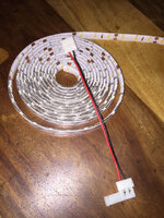
Here it is, the boring bit - I hate the fluorescent tubes in backboxes so I finally decided to do something about it and replace with some flexible LED strip instead.
So I bought a 5m roll that I figure should be enough for 3 or 4 games, and a few connectors, and now I just need to find a source of the 12V required. Then I looked in the manual and that just opened up a can of worms for me:
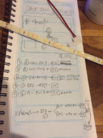
I started off by just looking for where 12V was mentioned in the schematics and found several places on 4 different boards which I jotted down on the notepad in the picture - some connector pins but also on a couple of fuses and on a bridge rectifier.
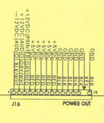
The power supply output CN2pin7 blue wire looks a good candidate, and presumably that is also the source of the +12V blue wire on the DMD control board. The other choice is J16pin2 grey-white or pin3 grey-red on the I/O driver board.





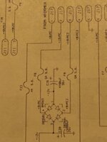
So I started looking at the I/O board schematic and it seems that the +12V going to J16pin2/3 comes from bridge BR3, which has two inputs and two outputs. Outputs are +12V DC and -12V DC, inputs are from J17 pins 2 and 3, 19V AC from the transformer via fuses F8 and F9 - but as written, it goes into the fuse as +19V AC and comes out the other side (at the bridge) as +9V AC. So WTF happened there? Can fuses be used to drop voltage?
So yes, here are my questions for the knowledgeable: which of the above would you use as a 12V source for this LED strip? Or none of the above and something else instead? And how did that transformer 19V AC turn into 12V DC, and is it a clean enough source?


And which of my looky-likey pics is the best? Putin, right?


Here it is, the boring bit - I hate the fluorescent tubes in backboxes so I finally decided to do something about it and replace with some flexible LED strip instead.
So I bought a 5m roll that I figure should be enough for 3 or 4 games, and a few connectors, and now I just need to find a source of the 12V required. Then I looked in the manual and that just opened up a can of worms for me:


I started off by just looking for where 12V was mentioned in the schematics and found several places on 4 different boards which I jotted down on the notepad in the picture - some connector pins but also on a couple of fuses and on a bridge rectifier.
The power supply output CN2pin7 blue wire looks a good candidate, and presumably that is also the source of the +12V blue wire on the DMD control board. The other choice is J16pin2 grey-white or pin3 grey-red on the I/O driver board.


So I started looking at the I/O board schematic and it seems that the +12V going to J16pin2/3 comes from bridge BR3, which has two inputs and two outputs. Outputs are +12V DC and -12V DC, inputs are from J17 pins 2 and 3, 19V AC from the transformer via fuses F8 and F9 - but as written, it goes into the fuse as +19V AC and comes out the other side (at the bridge) as +9V AC. So WTF happened there? Can fuses be used to drop voltage?

So yes, here are my questions for the knowledgeable: which of the above would you use as a 12V source for this LED strip? Or none of the above and something else instead? And how did that transformer 19V AC turn into 12V DC, and is it a clean enough source?


And which of my looky-likey pics is the best? Putin, right?
Last edited:

