Pinball info
You are using an out of date browser. It may not display this or other websites correctly.
You should upgrade or use an alternative browser.
You should upgrade or use an alternative browser.
Bally Kiss J1 conductors
- Thread starter Biff
- Start date
A frequently asked question when working on Bally and Stern rectifier boards is, "can someone post a picture of their wiring"? 
 www.pinwiki.com
Bally/Stern - PinWiki
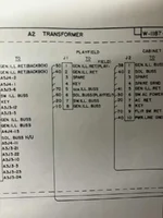
Thanks, pete. It shows the same as the drawings i have. No extra blue on j1. So still none the wiserA frequently asked question when working on Bally and Stern rectifier boards is, "can someone post a picture of their wiring"?
Bally/Stern - PinWiki
www.pinwiki.com
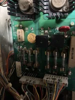
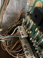
So if anybody has a kiss pinball, be great if you can take a pic on j1 on the PSU. Even the PSU has an extra pin that blue connects to. Drawing and wiki show 8 pins but mine has 9. See images higher up and below.

Look here: https://pinside.com/pinball/forum/topic/bally-rectifier-board-j3-pinout-paragon
Kiss, Future Spa and Space Invaders used AS-2518-49, which has 9 pins.
Kiss, Future Spa and Space Invaders used AS-2518-49, which has 9 pins.
Blatantly stolen from that thread (c) Quench:
J1 pin 9 only existed from factory on Ballys Kiss, Space Invaders and Future Spa. They had a different rectifier board (AS-2518-49) that used those two "R712E" TO-3 dual diodes to form the higher current bridge rectifier for the feature lamps.
As you probably know most of the aftermarket rectifier boards added that J1 9th pin as standard for compatibility with these three Bally games. It's caused a lot of confusion with people replacing their original 8 pin housings with 9 pin housings on their other games and counting the wire positions from the wrong end.
Bally used the 9th pin on these three games as an extra 6VDC feature lamp supply to the playfield.
Stern later decided they'd use the unused pin 3 for the same purpose instead of adding a 9th pin and modified their rectifier board accordingly.
It's all rather convoluted
Perfect, thank you makes sense. I am not a Bally expert. Not sure i am expert in anything, talking cod **** maybeBlatantly stolen from that thread (c) Quench:
J1 pin 9 only existed from factory on Ballys Kiss, Space Invaders and Future Spa. They had a different rectifier board (AS-2518-49) that used those two "R712E" TO-3 dual diodes to form the higher current bridge rectifier for the feature lamps.
As you probably know most of the aftermarket rectifier boards added that J1 9th pin as standard for compatibility with these three Bally games. It's caused a lot of confusion with people replacing their original 8 pin housings with 9 pin housings on their other games and counting the wire positions from the wrong end.
Bally used the 9th pin on these three games as an extra 6VDC feature lamp supply to the playfield.
Stern later decided they'd use the unused pin 3 for the same purpose instead of adding a 9th pin and modified their rectifier board accordingly.
It's all rather convoluted View attachment 286830


