What's new
Pinball info

Register a free account today to become a member! Once signed in, you'll be able to participate on this site by adding your own topics and posts, as well as connect with other members through your own private inbox!

Complete BALLY FLASH GORDON STROBE LIGHT RE-BUILD TUTORIAL

new forest pinball

Site Supporter
Joined
Oct 27, 2015
Messages
1,845
Location
brockenhurst hampshire
Alias
Keef.
Hi all ,
Having repaired/refurbished a fair few Flash Gordon pinball machines for clients, one observation is that not one machine had a working strobe light.(centre top backglass). So here is how we have been fixing them. Thought it might prove helpful as the strobe pcb and most parts are now becoming either impossible to replace or at the very best rare to find.
All strobe lamps are burnt out by now......a simple continuity test between the red wire and black wire connected to the lamp will confirm this. (Continuity should be present.). It will look something like this.........the case will be melted to!.....IMG_4096.JPG
First thing to do is to find yourself a new / replacement strobe lamp.....no point wasting time looking at all the pinball parts suppliers, none of them, and I mean none have a single one!..the secret here is to purchase the newest, old Polaroid 600 series camera you can find on eBay. This will cost you between £2.50 and £9.00 plus postage. Here is what I bought for this tutorial.....(costs £5.70 inc. post).
IMG_4089.JPG
Here it is unboxed..no problem if it's broken as long as the flash works...that's the bit we want!..............
IMG_4090.JPG
Now the incredible thing is that the flash / strobe lamp from these particular cameras is an exact fit with the Bally original strobe.
So next step is to carefully remove the flash lamp from the camera. There are no screws on this model just plastic clips and covers...
First remove the plastic panel that fits around the strobe......

IMG_4091.JPG
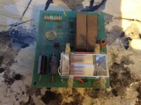
Then remove the complete pcb assembly from the camera......like this.......IMG_4092.JPG
Next job is to de-solder the flash unit from the pcb...leaving you this.......
IMG_4093.JPG
Then finally remove the strobe lamp from its plastic lens cover as it's a different shape to the Bally lens, on this model Polaroid, on some it's the same so you can use the Polaroid lens in place of the Bally one as it is almost always in a better condition. For this job we will be re-using the Bally lens. The lens is glued on with contact adhesive via two tabs either side of the lens....like this....IMG_4094.JPG
Now we have our new strobe lamp!.....fantastico!............to be continued......
 
Last edited:
Just to add here.. dont be trying that polaroid flash out and then installing it... You can get a decent amount of voltage akin to a cattle prod from one of these.. (usually from the Capacitor and associated circuitry that feeds the strobe) . I speak from experience...
 
Just to add here.. dont be trying that polaroid flash out and then installing it... You can get a decent amount of voltage akin to a cattle prod from one of these.. (usually from the Capacitor and associated circuitry that feeds the strobe) . I speak from experience...
Shocking!!!
 
Just to add here.. dont be trying that polaroid flash out and then installing it... You can get a decent amount of voltage akin to a cattle prod from one of these.. (usually from the Capacitor and associated circuitry that feeds the strobe) . I speak from experience...
I would have paid to have seen that, :p a bit like @Alan Syson woolly jumper LOTR repair.
 
I am revisiting this thread for several reasons....
1). I got distracted adhd style and never finished it...
2). We have repaired 3 or more boards since and have some additional faults to report that might be helpful....

If you have a completely dead strobe lamp, first check all your voltages on the connectors in the backbox that look like this..
55F9D75A-E66A-43C9-8DBA-5BD6B053AC3F.jpeg

Here’s a simple diagram of the circuit........ showing the pins and their functionality.

B47ADD01-0FD5-4D04-8A11-7E40B2DC3138.jpeg

Pin 3 and 1 ( Green and Orange). Should read about 115v ac. Pin 8 (Blue). is the switch bus illumination so that should read about 6.9v ac. Pin seven is the feed from the aux lamp driver board which gives the signal from the saucer shot. (Orange/Blue). Test this by activating the saucer switch and see if you get your meter to flicker voltage a few times. If all voltages are there, proceed to the next step.
Currently we hay a minty refurb in for Craig @roadshow16 , after repairing his strobe pcb and replacing the strobe (see below) on re-installing the pcb we noticed that the switch bus voltage was missing, although when removed it was present.🤦🏽‍♂️ The switch illumination bus comes directly from j3 on the power supply so we followed it back and found this! 😲

391D0570-29E5-4AE2-B4FA-3C5A2EB29573.jpeg

Once reconnected we had our switch illumination voltage back! Phew 😅......

Anyway here’s what else we did, and some other faults we have encountered in the past....
1). Dim strobe. This will be c2 and c3 replace with a 22uf 250v capacitors, easily found on the Internet.
2). Inoperative strobe but with all voltages correct. We have found this to be one of the following:
A). U1. Moc3011 an optical coupler I.c. Easy to find also. Replace.
B). Dry joints on the pins. - inspect and re-solder.
C). Q2. A c108c41 SCR PNPN Triac these are no longer available so we used a BT137-600 to replace original SC.

On the one we recently did the following was replaced....
C2 and c3, u1 , Pin’s reflowed and the strobe. Replacing the strobe this time around was interesting. Again we used a strobe lamp from an old 1978 Polaroid camera, but times have changed. In the posts above we paid £4.99 delivered for the old Polaroid, now they cost up to £125 - 150! Crazy. Eventually we made an offer on a faulty camera for sale in a charity shop, ironically the fault was leaking AA battery cells😂..... anyway here it is......

6AF97CD5-644A-4BFD-A3D6-AAEA05A7672F.jpeg

Then we toke it apart.....

8AFDCF91-2B11-466C-8293-49C0A18077E5.jpeg
Notice the huge capacitor! You can get a nasty shock of these so best to discharge first. I used one of @AlanJ led bars to do that....

33FC934F-4C5C-4E34-9995-BDBBB08C9A0A.jpeg

And here is the strobe lamp removed... notice the size of this lamp!! It’s more than twice the size of the Flash Gordon Original this is gonna look cool 😎...... the lamp has to be the three wire type. Just match the colours of the original. Worthy of note is some original lamps have a green wire instead of a white.
The white wire fits to the centre pin behind the strobe.

98E72F27-7DAD-4D00-8845-32B2ABA068D7.jpeg

And here is the new lamp installed it fits perfectly inside the original mounts. This was more luck than judgement, some I have done in the past are the exact same size as the Bally original.

Now we have a full working strobe pcb. Hopefully some help to someone......Keef👊🏼
 

Attachments

  • 504C2BCE-E8D1-4FFB-A375-48A114641B7D.jpeg
    504C2BCE-E8D1-4FFB-A375-48A114641B7D.jpeg
    133.2 KB · Views: 17
Last edited:
@new forest pinball Keef help please mate, sorry.
Installed new flash, I believe wiring is correct.

IMG_1039.JPG IMG_1041.JPG

Turned on, nothing happened. Checked voltages as per your checklist, 0v from "Pin 3 and 1 ( Green and Orange). Should read about 115v ac"
Followed the wiring under the playfield to the small transformer which had both connectors disconnected (alarm bells ringing 😏) hesitantly reconnected both, still 0v
Realised that the black plastic biro top style things were actually an empty fuse holder, checked http://www.pinballrebel.com/pinball/cards/Tech_Charts/Bally_Flash_Gordon_Tech_Chart.pdf
So tried a 1A SB as per that documetnt and it blew immediately :(

Don't suppose anything stands out here as incorrect? This what had been previously disconnected.

IMG_E1044.JPG
 
@new forest pinball Keef help please mate, sorry.
Installed new flash, I believe wiring is correct.

View attachment 191300 View attachment 191301

Turned on, nothing happened. Checked voltages as per your checklist, 0v from "Pin 3 and 1 ( Green and Orange). Should read about 115v ac"
Followed the wiring under the playfield to the small transformer which had both connectors disconnected (alarm bells ringing 😏) hesitantly reconnected both, still 0v
Realised that the black plastic biro top style things were actually an empty fuse holder, checked http://www.pinballrebel.com/pinball/cards/Tech_Charts/Bally_Flash_Gordon_Tech_Chart.pdf
So tried a 1A SB as per that documetnt and it blew immediately :(

Don't suppose anything stands out here as incorrect? This what had been previously disconnected.

View attachment 191302
Hi @Crewey
Assuming that the fuse is blowing with the strobe pcb disconnected. And the Then it’s the transformer at fault sadly.
Worth checking out for any shorts on the white plug though before it’s 100% the transformer. (Orange/blue/yellow cables)
Cheers Keef.
 
Hi @Crewey
Assuming that the fuse is blowing with the strobe pcb disconnected. And the Then it’s the transformer at fault sadly.
Worth checking out for any shorts on the white plug though before it’s 100% the transformer. (Orange/blue/yellow cables)
Cheers Keef.
Thanks for the reply mate, I disconnected the strobe power (green/orange) molex in the backbox which is the connection prior to the connector above and another 1A SB blew.
Other there being a short in that length of wiring to the molex in the cabinet then as you say it's the transformer. I put up a wanted ad earlier, I'm not sure how common they would have been though?

Cheers
Andy
its only a step down transformer that does 230v down to 110/115v

has it been wired properly for UK?
1673797887173.png

it needs to be 7 or 8 for UK - as std from USA will have been wired into position 6
 
hmm looks like it - unless someone swapped the wires around in the other socket? You have nowt to lose by trying it. (but donw plug into the strobe board - rather just see if fuse doesnt blow and you looking for around 115v a/c out of the transformer.
 
those pins can be a bitch to get out,if you don't have an extraction tool,unless luck is on your side
 
I’ve tried in position 8 & 7 which should be 240/220v as per above schematic, 0v on the meter but the 1A SB fuse is not blowing like it was on position 5 previously.

If anyone could check the pins on the step down transformer side incase these have been moved about, I have:

Pin 1 - Red (fuses to 4)
Pin 2 - white
Pin 3 - green/ yellow
Pin 4 - Red (fuses to 1)
Pin 5 - black/ white
Pin 6 - black/ yellow
Pin 7 - Black
Pin 8 - black/ red
Pin 9 - empty
 
Suppose I can try positions 6 & 4 to totally rule everything out, it’ll just cost a couple of fuses at worse and will confirm if it’s dead.
 
@new forest pinball fitted a different step down transformer and am getting ac 110/120v via one side of the twin wiring now at least.

On the explanation you mention I should be getting this voltage to both pin 1 & 3, following backwards with a multimeter I seem to be getting 240v on the live side (pre step down transformer) but on the neutral side 0v all the way along.

I’m also convinced that I incorrectly soldered the flash onto the board as I followed existing wire colours
 
New step down transformer, the old one was definitely a dud. Couldn’t get any voltage out at all.
 
Back
Top Bottom