Addams Family Pinball
Miscellaneous
This page is broken down into seven parts:
1. Updating your software: (changing EPROM's)
2. EPROM sources
3. Repairing your Dot Matrix Display
4. Adding an 'extra ball' buy-in button
7. Cows
1. Updating your software: (changing EPROM's):
More detailed instructions are provided if you purchase a ROM kit from me.
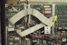
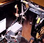
Changing your software is actually quite a straight forward procedure. First, make sure the game is turned OFF. (Personally, I leave the machine plugged in because you ground yourself when you lean on the side rail to put the chip in.) Remove the translite / backglass. Open the door and locate the EPROM's (see picture). Then just pop out the old EPROM(s), drop in the new one(s), reset all of your game settings (pricing, volume, etc.), and you're ready to play again.
An IC extraction tool is highly recommended for removing the old eprom, but a small flat blade screwdriver works wonders as well, just slide it under and pop it out of the socket. When inserting the new eprom, the two factors you need to worry about are not bending the pins and making sure that it the chip is inserted in the right direction. There is a small notch in the socket and one in the eprom as well, just line the two up and you're set!
To upgrade TAF (L-4 or lower) to L-5, only U6 needs to be replaced. U18 is the TAF sound rom and is the same for all releases of TAF.
To upgrade TAF to TAFG, U6 (the game rom) and U18 (the sound rom) need to be replaced. U15 (the second sound rom) needs to be added. To get at the sound roms, you need to remove one of the ribbon cables connecting the sound board to the display board. Don't forget to reconnect this cable after you've changed the roms.
If you have any more questions, feel free to email me at: taflist@shaw.ca
Picture of boards inside the back box, upper left side.
2. EPROM sources:
There are a number of different places you can acquire new software for your games. Some of the ones that I know about are:
Brian Dust (me): I have a large inventory of EPROM's, and can provide software for most newer pinball games (Bally, Williams, and Sega / Data East). I also stock EPROM pullers. Please see my '4Sale' page for pricing.
Mike Romco: Hosts an Addams Family web site with many repair tips, links, items for sale and other stuff. Visit at http://www.geocities.com/tafpinball/ .
Ray Johnson: Action Pinball & Amusement: An excellent source for practically anything you need.
Marco Specialties: Another great source for pinball parts and software.
John's Jukes Ltd.: Yet another good source for everything Pinball, Video, and Juke Boxes.
3. Repairing your Dot Matrix Display:
Your dot matrix display (DMD) may have just one row or column that does not work. This is a common problem with DMD's. There are a several options to take care of this problem.
1. The easiest, but most expensive, way is to replace the entire thing. This should provide with a nice, new, crisp display with no burn-in. Of course, if you leave your game on, the DMD will get burn-in again... New displays can be purchased from Ray Johnson and Marco Specialties for around $150us.
2. The other way is to try and repair it. Here is the method that I used. I'm sorry that I don't have any pictures, it was the only one that I've had to repair and has now been working for 4 years with no more problems. Chances are that the metal legs are broken right where they enter into the glass. Some people have suggested to try and solder it back together but that's extremely difficult since you can't heat up the piece of metal that is inside of the glass to form a good bond. What I did was pull the broken leg back and try to scrape some of the grey resin stuff off from the metal inside the glass. Then I turned the game on and in the display test mode (that lights up all of the pixels), I bent the leg back into the glass (preferably with something non-conductive since you don't want to electrocute yourself). When the two peices of metal touch you should be able to get the line to light up. Next, I wedged a toothpick in such a way that the line continues to stay on. (Basically, over the leg that was broken and underneath the 2 legs on eithier side of the broken one.) Then I got some five minute epoxy and spread it over the metal leg that was being held down. You have to be careful that the epoxy isn't too runny (i.e.: let it sit for a minute or two before putting on) so that it doesn't flow where you don't want it to. Even though it is five minute epoxy, I found that it was still best to let it harden overnight. Using this method, I managed to repair both broken lines on my DMD. Also since the epoxy doesn't stick perfectly' to the glass, it is possibly to remove it and start over (with a fair bit of work). I also spread epoxy over the rest of the wires where they entered into the glass, I feel that this ensures that more do not break and seperate.
CHERRY attempted fix coming soon!!!
3. Another potential method of repair is to use a conductive epoxy or "'rear window defroster repair kit". I haven't tried this but you would have to be careful to only connect each individual wire and not spread it over several of the wires.
4. Adding an 'extra ball' buy-in button:
This is the method I used to add an 'Extra Ball' button to my TAF to utilize the buy-in feature of the "Gold" software (see previous information on upgrading your software). Obviously, there are other (and likely better) ways to do it. I tried to use tools that I had on hand do it as inexpensive as possible. The total price of adding the button was approximately $27canadian. I would like to recommend that you have some minor carpentry, soldering, and electronics skills, but it's not a necessity.
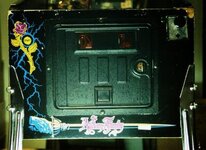
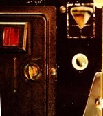
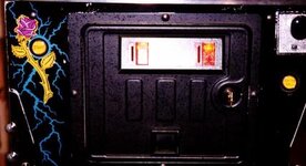
Here is the unaltered front view of my Addams Family cabinet.
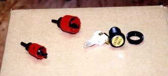
The tools I used for drilling out the hole.
From left to right: 1" hole saw, 1 3/8" hole saw, yellow Extra Ball button (p/n 20-9663-9). You also need one diode (1N4004 or equivalent) for the lamp, approximately 15 ft of 24 gauge wire, a couple of cable ties, a wire cutter, a drill, sandpaper (to clean up the hole), and some touch-up paint (semi-gloss black).
Starting the hole.
The center of the hole is 2" down from the ball shooter and 2" over from the side. The best thing to do is to take out your 'Start' button and try to make the new hole for the 'Extra Ball' button the same as the hole for the 'Start' button.
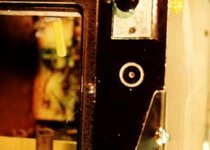
This is the hole I ended up with.
I started with the larger hole saw and cut in as deep as the 'Start' button sits. I then used the smaller hole saw to cut the hole right through. Use the button to make sure that it sits correctly in the hole. There is also a 'key' in the top of the button to prevent it from spinning in the hole. I used a haxsaw blade to put a small notch in the top of the hole for this 'key to fit into.
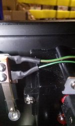
Inside the front right corner, the hole goes through part of the corner brace. You can also see the green wires (bottom-middle) that I have strung in for the switch.
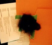
Painting the hole.
I just masked it off and used some black spray paint.
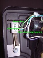
Adding the wiring for the switch.
You can run the wires all the way from the backbox or you can connect them to other items that are in the same row or column of the switch matrix. The buy-in button is number 11. The easiest way is to connect one wire from the white-brown side of the 'Slam Tilt' on the coin door to one side of the 'Buy In' switch. The other wire goes directly from the green-brown side of the 'Plumb Bob Tilt' (the hanging weight) to the other side of the 'Buy In' switch.
J208-1-------./ .-------J206-1
wht/brn switch grn-brn
Adding the wiring for the light.
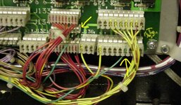
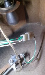
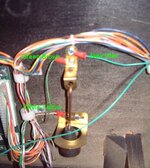
These are the wires in the lower right of the backbox. You can see the two green wires that I have strung up for the lamp on the button. It is number 41 in the lamp matrix. One to J134-1 and the other to J138-4. I soldered J134-1 with the diode (band closest to the pcb) instead of adding it onto J133 or buying a small Molex connector. The other wire just pushes in to J138.
J134-1----|<|-----O-----J138-4
power bd. diode lamp power bd.
This is the finished front. The picture isn't really the best and I should really fix up that chipped paint...

7. Cows
Explanation: xL: press left flipper button x times.
xR: press right flipper button x times.
xS: press start button x times.
In order to display the cows, you must not have any credits on the machine. You also can't be set to "Free Play" mode.
The Addams Family
During Attract mode, press the following sequence:
Cows: 7L, 1S, 14R, 1S, 20L, 1S
DOHO can be seen on the chain saw blade which the cow on the right is holding.

Design Team: 13L, 1S, 1R, 1S, 2L, 1S
The Addams Family Gold
The same as for TAF, plus:
Cows2: 12L, 1S, 5R, 1S, 4L, 1S

Cows for other games can be found at:
http://w1.853.telia.com/~u85304218/Cows&Easter.htm

