What's new
Pinball info

Register a free account today to become a member! Once signed in, you'll be able to participate on this site by adding your own topics and posts, as well as connect with other members through your own private inbox!

In Progress A Big Box of Bally Boards

Nedreud

Registered
Joined
Feb 12, 2013
Messages
3,092
Location
Aldershot, UK
Thought it might be interesting, and hopefully useful, to keep a log of my findings as I attempt to fix a big pile of old solid-state Bally boards.

Here's what I started with:
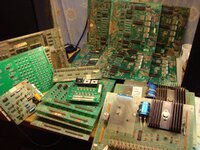
Bally Boards 002.JPG

Right at the back are 6 x AS-2518-35 MPU MODULE boards.
Front-right is a pile of 3 x AS-2518-22 SOLENOID DRIVER / VOLTAGE REGULATOR boards.
Front-middle is a stack of 4 x AS-2518-23 LAMP DRIVER MODULE boards.
Sat on top of those is a Rottendog replacement for an AS-2518-18 RECTIFIER BOARD ASSEMBLY.
Just behind that is an AS-2518-52 AUXILIARY LAMP DRIVER board.
In the lower-left is an AS-2518-50 SOUND MODULE from, I think, a PARAGON.
The modern bright green board behind that is an ALLTEK ULTIMATE LAMP DRIVER BOARD.
And at the back upper-right is a WILLIAMS 1B-2001-131-2 DRIVER BOARD for System 3-7 machines.
Finally, there was also a BALLY MPU CORROSION REPAIR KIT (not pictured).

I'm very pleased with that little lot! The Rottendog rectifier is a drop-in replacement for my PARAGON, so that's a keeper. The sound board will be handy too if it's from a PARAGON because mine occasionally makes a few duff noises. The aux lamp driver is used in VECTOR, so handy to have a spare.

The Alltek lamp driver is a very pleasant surprise. On initial inspection I can't see anything wrong with it other than a few connector pins that got bent during transit. It's so modern I can't believe it's failed already. Also, Alltek offer a lifetime warranty as long as " it doesn't look like it has been run over by a truck." I wanted to try converting my VECTOR to LEDs so it's ideal as it solves all the LED flicker problems with any modifications to the rest of the machine.
 
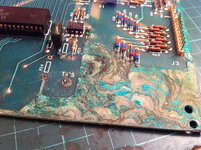
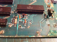
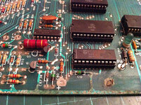
I started having a bit of a poke with the MPU boards this evening. Considering they're all the same AS-2518-35 board it's amazing how different they all look. One is a lovely dark glossy green PCB and there's quite a variation in the components, especially the chip sockets. All of them have acid corrosion of some sort. Only one looks particularly bad.

I started to identify the U1/2/6 ROMs:
  • U2 748-15 and U6 720-30 are from a PARAGON, but U1 748-17 is missing although a U2 786-17 from SILVER BALL MANIA was in it's place!
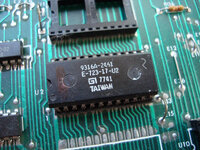
  • U2 723-17 from an EVIL KNIEVEL
  • U2 723-20 from an EIGHT BALL
  • An EPROM marked as 842-08 which is a U2 from FATHOM
I tried each of them on the bench power supply: 3 of them are totally dead - no LED at all. 2 of them the LED is on constantly, but after pulling out a 6810 RAM from the U1 socket and returning it to the correct U7 socket one of the boards actually managed the initial flicker and 2 flashes! That tells me the ROMs and U7 are good, but is failing on the next test which is the U8 5101 SRAM. Looking closely at the board the U8 socket has a bit of acid corrosion although it came off lightly elsewhere. Amazingly, I think all 6 MPUs still have their 5101 chips. They could all be toast but hopefully one or two are ok (they're worth a fiver each alone).
 
Another quick test this morning: pulled all the 5101 SRAMs and tested them in the PARAGON MPU. Out of 6 only 1 isn't chuffed. Still better than nothing. Another £5 I won't be spending.
 
Couldn't resist... popped the working 5101 SRAM into the MPU that was getting 2 flashes and got the third flash! Yay! Why no fourth flash? A-ha! Missing U10 chip. Popped in a spare 6821 PIA and got all 6 flashes. Happy days, a fully working MPU for just 10 minutes basic diagnostic work, no soldering required. Surprising thing is visually it's the got the worst corrosion damage of all six boards. Will need to strip off the affected components, neutralise and refit components, new sockets and connectors, etc., but basically I have another £60 Bally MPU :D

The number on the original masked ROM doesn't seem to match any of the reference charts on-line, e.g., http://www.pinrepair.com/bally/roms.htm:

farm6.staticflickr.com_5607_15491372851_fe4632f2ce_c.jpg

But checking in the 1982 Bally Parts Catalog I see the right codes. So it's an EIGHT BALL! It seems I have two sets of EIGHT BALL ROMs, with the E-723-20 being listed as only for an unmodified AS-251-17 MPU (there was a service bulletin F.O.597 to modify the early boards for use with an electronic Sound Module):

Code:
U1          U2          U6           GAME              NOTES
----------- ----------- ------------ ----------------- -----------------------------------------
            E-723-17    E-720-20     EIGHT BALL        Use with AS-2518-35 or any AS-2518-17 MPU
            E-723-20    E-720-20     EIGHT BALL        Only use with unmodified AS-2518-17 MPU
            E-748-15    E-720-30     PARAGON           Needs E-748-14-U1
            E-786-17                 SILVERBALL MANIA  Needs E-786-16-U1 and E-720-35-U6
E-792-10    E-792-13    E-720-35     SPACE INVADERS
            E-842-08*   E-720-53     FATHOM            * = EPROM

I love this stuff! I am the Sherlock Holmes of Bally solid-state research.
 
Thanks. I Googled for "Bally 723-17" and "Bally E-723-17" but that page didn't turned up in the results! Just tried again searching for "Bally E723-17" and it's the top hit o_O

Seems as though the massive production run of 20,230 units spanned the switch from the "early" AS-2518-17 MPU to the "later" AS-2518-35 MPU, hence why there are so many ROM sets for this game.
 
I had a Eight Ball, which was using a Stern Mpu-100 when I acquired it. The 100 seems to be exactly equivalent to Bally's -17 Mpu board.
And I think the M-200 is the same as the AS-2518-35. It's all something to do with Stern buying the company that used to actually make the boards, which included the design, hence why two separate (rival) pinball companies used kit that was virtually interchangeable! The only major difference was the software on the ROMs. Bally used to re-use the core program on the U6 chip across several games of the same generation, whereas Stern compiled a unique U6 for each game.
 
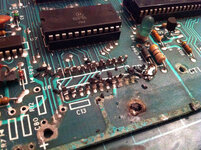
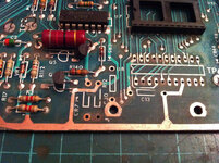
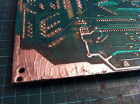
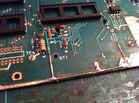
Managed to work on repairing the battery corrosion damage on the working MPU over the weekend. Here's what I started with:

farm6.staticflickr.com_5600_15341068527_14f10eb3c9_c.jpg

farm6.staticflickr.com_5600_15341019388_d392c44ebb_c.jpg

The reset circuit section got off very lightly on this board. Most it was the lower right-hand corner that was worst affected. The battery acid had just touched CR7, C80, R12 and C13. It had just about made it to the bottom edge of the socket for U8. These sockets are notorious for making poor connections so any opportunity to replace them with a decent turned-pin socket is a good one. When I did this on the MPU from GOLD BALL I found a broken track under the socket! The design is rather nasty under U7 and U8 as there are tracks going between the pins on the topside:

farm4.staticflickr.com_3949_15341019028_e4d3aef1c8_c.jpg

Hacked of the plastic chassis of the socket for U8, the 5101 SRAM, leaving the pins behind to unsolder one at a time. You can see pins 9, 10 and 11 have gone fuzzy and grey:

farm6.staticflickr.com_5611_15341017178_1799afb227_c.jpg

After removing all the components that had been tinged with corrosion (CR7, C80, R12, C13, C16, R23, C17, R24, C37-40 and TP5) I stripped off the corroded solder using a fine 1" flexible sanding disc on the Dremel:

farm6.staticflickr.com_5601_15527278592_95c6337395_c.jpg

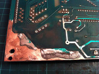
The underside was affected too, here near the U12 555 display interrupt generator. I managed to get those great globs of solder off eventually!

farm4.staticflickr.com_3956_15340771509_2db60aae86_c.jpg

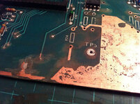
What looked ok to start with is revealed as quite severe damage once the solder is gone. The ground plane near TP5 is completely shot. The battery connection is completely isolated, but this isn't critical as the ground plane forms a complete loop around the board. R24 was effectively the only disconnected component, which, as far as I can see, is a pull down resistor on CB1 of the U11 PIA:

farm6.staticflickr.com_5604_15527279672_33a574c751_c.jpg

After sanding off the corroded solder I used an artists brush to soak the exposed ares with white vinegar (an acid) to neutralise any remaining electrolyte from the NiCad battery (alkaline) then rinsed the board with warm water. I then flushed with isopropyl alcohol to drive out the water and finally dried the board with a hair dryer.

Next I started to reflow solder on the underside tracks. Not sure if it's the new soldering station or the solder but I had quite a time getting it to flow across the large areas (I didn't have this problem on my PARAGON MPU). The solder seemed "mushy" and I ended up turning the temperature up to 400°C. The new iron certainly gets hot (and quick) but doesn't have the same reservoir of heat as my fixed-temp 25W Weller iron. Must get some more high-quality fine solder too:

farm6.staticflickr.com_5606_15341012428_b638ddae76_c.jpg

I fixed the gaps in the tracks by laying down solid wire:

farm6.staticflickr.com_5604_15527277052_57322b885c_c.jpg

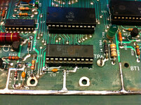
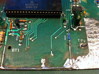
And then replaced all the components. God, my work looks terrible in these photos! My soldering is usually much better. It's clean enough but it's so ugly! Will look a bit better after cleaning off the flux gunk with PCB cleaner. Also lost a couple of topside solder pads, e.g., bottom of C80. Not critical for electrical connectivity as just a pad with no track (the circuit is on the underside) but makes a solid physical connection:

farm4.staticflickr.com_3927_15524572851_37572401f2_c.jpg

farm6.staticflickr.com_5601_15341078218_d5b9eec8ae_c.jpg

But cr@ppy soldering aside the good news is I have the first corrosion-free working MPU rescued from the big box of Bally boards! If I can't fix the MPU from GOLD BALL, that's where this one is going.

 
October 2015
AS-2518-61 Rev.b SQUAWK & TALK


Been a long time since I posted on this thread but have the weekend to myself so time to get some of these old Bally boards working again. And my Bog Box of Bally Boards has expanded with the addition of 3 AS-2518-61 SQUAWK & TALKs!

First up, is a dead S&T. This one came with @astty's VECTOR project. Unfortunately testing it killed the -12VDC power on my ATX power supply. Closer inspection reveals two broken caps: C13 0.1uF ceramic disc which I think is a bypass filter on the +5VDC supply to the TMS5200 speech chip (missing) and C45, another 0.1uF ceramic disk part of the input to the U14 VCA (Voltage Controlled Amplifer), has snapped a leg. Not sure how these could have toasted the -12VDC supply yet...?

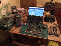
So, here's the test rig. Laptop to run Hantek6022BE USB oscilloscope and reference PDF schematics, Maplin Precision Gold WG020 multi-meter (pay attention @Will), old ATX computer power supply for +5V, +12V and -12V, soldering iron and Arduino MEGA 2560 to take the place of the MPU for supplying digital control signals:

farm6.staticflickr.com_5729_21981396493_582cd7bc58_c.jpg

I've wired up a 15-pin 0.156" Molex connector with Ground on pins 6 and 16, +12VDC on pin 10, and Arduino jumper wires for the data signals on pins 1, 2, 3, 4, 8 and 12.

At switch on I'm not getting even the tiniest twinkle out of the test LED. This isn't a good start as the first time I powered up this board (when it killed the -12VDC on the ATX) I got flashes. So, first things first check I've got +5VDC at TP2? To do this set the multi-meter to 20V DC range, put the black probe on TP1 (ground) and the red probe on TP2 (+5V). Getting a nice steady

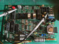
Next, is the CPU generating a clock signal? Yes, the a nice high-frequency +5V square wave pumping out of pin 37 "E" on U1, the Motorola MC6808 CPU, which is the external clock signal.

farm6.staticflickr.com_5726_21979786934_cae39d02c5_c.jpg

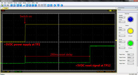
After that it's time to check the RESET circuit. This is much simpler than on the MPU boards (thank god). I hooked up the oscilloscope to be triggered on Channel 1 by the power on of the +5V at TP2 anduse Channel 2 to monitor the reset signal at TP12:

farm6.staticflickr.com_5754_22414658460_b5944b51cf_c.jpg

That looks ok. A nearly 300ms delay to allow the power to stabilise before resetting the CPU to start booting.

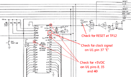
Here's what I'm testing on the schematic. Without power, clock signal or reset signal the CPU isn't going to do anything. No CPU, no S&T!

farm6.staticflickr.com_5764_21985351874_b700747b8e_o.png

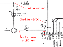
Next it's time to look at the CA2 data on pin 39 of U11, the MC6821 PIA (Peripheral Interface Adapter), which controls the flashing of test LED1 via Q1 and R7. First I checked U11 to make sure it's got a good ground connection on pin 1 and +5VDC on pin 20. Next check that R6 is getting +12VDC to actually power the LED. So far, so good.

[url=https://flic.kr/p/ArQj42]farm1.staticflickr.com_608_22608468615_a45d442267_o.png

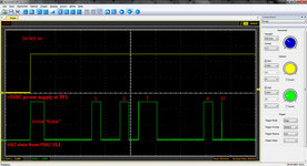
Channel 1 of the 'scope stays on the +5V TP2 to trigger the trace when the power is switched on. Channel 2 is connected to the base of Q1 (the middle leg) to see what it's getting from U11:

farm1.staticflickr.com_727_22019100223_374f44ac1c_c.jpg

A-ha! So there is life from the PIA! So, the LED is being fed +12V (limited by R6) and is being sent a control signal from CA2, pin 39 on U11, but no flash. I removed the LED from the board and it works when connected to +5V. The conclusion therefore is that Q1 2N3904 is chuffed.

I'll finish this post here. I'll replace Q1 and be back with more...[/url]
 
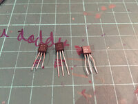
A mentioned in my last post the prime suspect at the moment is Q1, a 2N3904 small signal NPN transistor, so I removed it from the board for testing. For comparison I had a couple of spares, one pulled from old MPU and another brand new:

farm1.staticflickr.com_766_22455410720_42a630092e_c.jpg

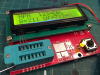
For accurate testing I use my little ESR/LCR meter. First up the brand new 2N3904, which tests ok with a gain of 211:

farm1.staticflickr.com_608_22617321516_5f75277c9a_c.jpg

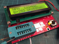
Next up the old one pulled from an MPU, which is also ok with a good gain of 283:

farm1.staticflickr.com_588_22617317976_3b03d97419_c.jpg

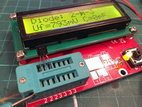
And finally the suspect one removed from the S&T:

farm1.staticflickr.com_712_22020562134_3965c530e7_c.jpg

That's not right! The tester thinks it's only a diode between pins 2 and 3 (base and emitter). It's dead!

I fitted the new transistor and popped a new LED in for good measure:

farm1.staticflickr.com_607_22617926586_1777fb012d_c.jpg

Keeping soldering neat as possible on the underside (clean the flux residue off with a little IPA later although once this board is working it's going to get a thorough wash):

farm1.staticflickr.com_676_22617927526_d8b2070cf9_c.jpg

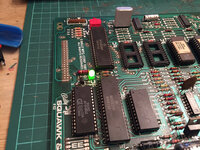
Powered it back up and flashes galore!

farm6.staticflickr.com_5695_22617927296_1b880f06c2_c.jpg

Only getting 4 flashes at the moment as this S&T has no TMS5200 speech chip. Got to replace a couple of broken ceramic disc capacitors beforehand.
 
Last edited:
having to do the same thing on my bally mpu board,
replace the reset circuit mine was not as bad as yours
i'm going to use the DS1811 reset chip
 
more interesting mcp130 got a 5k pull up resistor built in,
the 1k pull resistor used with the d1811 delays the first flicker
so more like a flash would a 5k resistor make the flash even longer?
next question where did you get green led for cr8 is it a 12v 5mm one
i binned mine and it doesn't say in manual what value it is?:hmm:.
excellent write up on repairing your boards:thumbs:
 
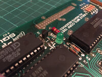
The green LED is "bog standard" 5mm one I stole from my sons box of Arduino electronics! Originally I think it was from a selection pack from Maplin. It's standard brightness, probably around 20-30mA current. Although it's supplied by the +12VDC unregulated power the 1/2 Watt 470 Ohm resistor R6 limits the current.

According to Maplin:

http://www.maplin.co.uk/p/5mm-green-led-wl28f

My LED has a forward voltage of 2.5V and a forward current of 25mA so the required resistor value is a a 1/2 Watt 390 Ohm according to this calculator:

http://led.linear1.org/1led.wiz?VS=11.9;VF=2.5;ID=25

The fitted 470 Ohm R6 is therefore just fine. They probably chose this value as their LED may have needed only 15-20mA.

As for the MCP130 you need to pick a trigger voltage as there's a whole range. Unlike the original circuit which just provides a 50ms delay because it assumes the +5VDC power has stabilised within that time, these devices actually monitor the supply to ensure a threshold voltage has been maintained for a certain time, up to 700ms. You need to analyse the datasheet closely to select the most appropriate device. At 700ms that initial "flicker" could end being the longest flash! Not that it matters, the CPU just won't start running till it gets the reset signal.
 
Back
Top Bottom