What's new
Pinball info

Register a free account today to become a member! Once signed in, you'll be able to participate on this site by adding your own topics and posts, as well as connect with other members through your own private inbox!

TZ - G.I. doesn't dim (FIXED)

Durzel

Registered
Joined
Oct 1, 2017
Messages
2,041
Location
Bath, UK
I have a feeling this isn't an easy or cheap fix..

I discovered tonight that my G.I. doesn't dim. I figured because I had LEDs in there that this was normal, but when I fit the LEDs to my friend's Funhouse his G.I. flickered/strobed something fierce when I went down the brightness settings in the test menu. Anyway, something @Monkeyboypaul said earlier prompted me to check mine for strobing, when I discovered the problem. Since I bought the pin with these bulbs already fitted, it's quite possible the problem has existed since I bought it.

Unfortunately (for me) Standard adjustment 25 is already set to "Allow G.I. Dim" = YES (default). I'm aware that setting this to NO blocks G.I. dimming in test mode too.

All of the G.I. works, but none of it dims. Brightness levels 1-8 do not alter the brightness in any way.

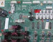
I put an incandescent bulb in the right slingshot, thinking perhaps the LEDs were non-ghosting or otherwise compensating, but that doesn't dim either - so definitely a board problem somewhere.

I've reached the end of my capabilities really. A cursory search seems to point to a "zero cross" thing being the next thing to test. I don't own a scope though, and wouldn't have the first clue how to use one if I did.

I'm happy to pay someone to come out and take a look at it. The pin is located near to Bath, BA2 postcode.

Thanks in advance :)
 
Well, I'm aiming to fit a GI OCD kit soon. If that relies on this "Zero Cross" or whatever else might be faulty, then that's not going to work either.
 
In Test 6; General Illumination: Running

Do the individual strings work? ...as in does correctly light different zones on the playfield separately in the test?

As Pinside Cayote says: using an incandescent in 1 GI socket will help.

...also check:

A1. 25: Allow Dim Illumination: YES.

A1. 29: GI Power Save: maybe 2mins?

A1. 30 Power Save level: maybe 4?

(Then wait 2-3mins in attract mode for GI to dim)

A2. 29 Low Line: NO

NOTE: i won't be able to reply til Tuesday after c.o.p. today (no mobile signal)
 
Last edited:
Will have a look tonight and report back.

All the individual strings work and switch off as expected. Nothing fails to illuminate, each zone comes on (with the rest off) as you'd expect.

Incandescent in right slingshot G.I. socket didn't dim either.

A1. 25 already YES. Do I need to switch the machine off and on to "reset" that? I'd already read that this setting being NO inexplicably affects the G.I. tests.

A1. 29 and 30 almost certain will be factory (as I don't know what they are)

Thanks.
 
All of the above settings are their defaults.
G.I. doesn't dim in attract mode.

Reseated ribbon cable between power driver board and the board with the ASIC on which made no difference.

If anyone is local to me and has a scope or something who can tell me if the ZC is knackered, or something else, I'd appreciate it and be happy to pay. I've tried emailing a couple of local places but they're either unable to do board work or unable to come out. :(

As trivial and non game breaking this problem is, I'd like to resolve it so I can use a GI OCD board.
 
Dimming the gi would surely work by lowering the voltage right? Do you have a meter to test that with?

Also, if it does work by lowering the voltage, then replacing a single led with an incandescent bulb will barely make a difference as Leds use so little power. So even on the 'dimmest' setting the incandescent will be receiving far more wattage than originally designed
 
True, but I would've assumed that something would happen as the LEDs received less voltage, either they'd strobe, switch off prematurely or whatever.

My friend's Funhouse - which admittedly has cheaper LEDs - actually dims slightly as you change the GI level in test, and strobes on a couple of levels.

Will try checking voltages though, assuming that's how it dims (I thought it was done differently as I believe it's AC power?)
 
Oops, yes you're right of course. GI is ac, and I always forget this. Ignore my post entirely
 
Check connection and wire at j115 pin 1 . This is the ground reference pin for the GI and is necessary for dimming GI.
 
Check connection and wire at j115 pin 1 . This is the ground reference pin for the GI and is necessary for dimming GI.
J115 looks solid. It's been repinned in its life (now a black connector). All the wires look secure. I removed the connector and reinserted it without any change in behaviour.

Would it help to get photos of the boards? I've read about BR2 traces etc being a prime suspect of GI dimming not working, but I can't see anything obvious there. I can't even tell if BR2 has ever been replaced.

As said I'm more than happy to pay for someone's time to come out and tell me what is wrong. If that then involves taking a board out to be shipped off for repair - that's fine.

Without a scope and no obvious wires loose that I can see I'm a bit stuck on how to progress this.
 
Could try that. The number of connectors etc is pretty intimidating though. Have never tried to do that kind of job.
 
Just take tones of pictures, if they have rows two deep, take one of top row with colours and then on the bottom one, then install backwards lol.

It isn't hard, I can do it!
 
Oh and not to be obvious, but these are the silly mistakes I have made, just loosen screws and lift off the board up by pulling up, don't take ALL of he screws actually OFF :)
 
Ok. Thanks all.

FH isn't mine so don't know how happy my friend would be for me to potentially break his machine (as said, I'm not confident with this stuff), or even have it out of action for too long.

I'd much rather pay a professional to come over and diagnose and if needs be remove board(s) for repair.

Appreciate the feedback though.
 
The primary cause of GI lamps failing to dim is broken traces at BR2, usually caused when BR2 was replaced. These traces lead to D3 and D38. Both of these traces must be intact for dimming to work as they supply the power to generate the signal to the Zero Cross circuit (ZC) which is key to dimming.

Check these traces!! I had the same fault in my Addams Family and it was a broken trace to D3.
 
Thanks. Do I need to remove anything to see these traces? BR1 and BR2 are covered with a big silver heatsink.
 
No. Just use your DMM and buzz the traces.
Sorry to be a pain but could you (or someone) explain exactly what that means?

I have a basic DMM. Which setting would I need to put it on? Where would I put the red/black probes? What reading should I expect to get? Pin off or on?

I assume it's a continuity test?

I don't actually know where D3 is, is it marked on the board like BR2 is?

Thanks again.
 
Pin off.

DMM on continuity test. Put one probe (red or black doesn't matter) on the start point of the trace and the other on the end point. If you have continuity, you will hear a buzz sound. If not the trace is broken somewhere (mostly at the solder pads).

Test also the 2 diodes. Red and black at both ends. In one way you should read nothing on the DMM. Then switch both probes and you should read something from 0,4-0,6.
 

Attachments

  • WPC Power Driver Board D38 und D3.jpg
    WPC Power Driver Board D38 und D3.jpg
    193.2 KB · Views: 26
Last edited:
Thanks.

Think I'll have to get someone out.

Couldn't get consistent readings on those diodes, DMM just read 1 or briefly different numbers. Obviously not using DMM properly or it's not working. Tried several other diodes and had much the same results.

Don't know where the start and end points of the traces are or how to locate them.

As said I'm very much a novice with this stuff and need someone to come out and help me :(
 
I found this guide invaluable in describing the tools and electronics present in pinball machines when I started out :-
http://www.pinrepair.com/begin/#howdmm

A lot of DMMs have a diode test function, perhaps posting a picture of your DMM will help us help you.

Good idea getting somebody to visit too, some people like learning that way:thumbs:
 
For what it's worth I took some photos in case anything obvious stands out.

4BC0A318-5337-4F43-8020-99281687A5E3.jpeg
025D1E11-40DE-416C-A245-3D18BACBDCFB.jpeg
CD703DA1-7B55-4FBF-B34C-B43FDB6AA214.jpeg

There are two connectors not attached to anything. I don't think that's related to this problem, as everything works normally, but just thought I'd mention it. The one that goes up towards the top right of the backbox is marked "609" on the connector (by previous owner or someone)

628D5E17-EB88-4A3D-AB22-EE7D8A65B11E.jpeg
4866FF4F-8752-41D8-B686-D05764CFEA01.jpeg
 
I found this guide invaluable in describing the tools and electronics present in pinball machines when I started out :-
http://www.pinrepair.com/begin/#howdmm

A lot of DMMs have a diode test function, perhaps posting a picture of your DMM will help us help you.

Good idea getting somebody to visit too, some people like learning that way:thumbs:
Here's a photo of the DMM I have. It's a pretty cheap thing.

026F17CC-FC24-4CBE-BE7A-AE5F41D87A1D.jpeg

I realise it's the black speaker symbol for continuity and ohms symbol for resistance to check the diodes.

I don't know where the start and end points are to test the traces, and when I was testing resistance (no idea what level I needed to use - 200, 2000, etc) I couldn't get consistent results with any of the diode legs I was touching with the probes, which makes me think I'm just using it wrong.
 
You have it on the wrong setting, you need it, its the black one with the triangle, that's also the continuity test. Re-check your diodes on that setting as explained. To test the traces, you simply put it on either point that should be connected and it will beep.

The only 8 pin socket I can find so far (I don't own a TZ) is J212, thats on the long board on the left, labelled as such... It looks like something is plugged into that though. Can you take a closer picture of that for us please. It's on the left board under the big chip bottom left.
 
You have it on the wrong setting, you need it, its the black one with the triangle, that's also the continuity test. Re-check your diodes on that setting as explained. To test the traces, you simply put it on either point that should be connected and it will beep.
I put it on the black one to test the diodes? The one that buzzes if I touch the probes together?

I assumed that the diode test was a resistance one based on this...
Test also the 2 diodes. Red and black at both ends. In one way you should read nothing on the DMM. Then switch both probes and you should read something from 0,4-0,6.

Regards this..
The only 8 pin socket I can find so far (I don't own a TZ) is J212, thats on the long board on the left, labelled as such... It looks like something is plugged into that though. Can you take a closer picture of that for us please. It's on the left board under the big chip bottom left.
Here you go..

J212 is a much thinner connector so I don't think it's related.

203E2347-CDC8-411D-A47E-A9C2D9FBE0B0.jpeg
 

Attachments

  • D06E8C8E-7968-4573-944E-38FF397A138F.jpeg
    D06E8C8E-7968-4573-944E-38FF397A138F.jpeg
    201 KB · Views: 11
Can you trace where those wires come from please, or do they go into cabinet?

Yes the black is both diode and continuity on that DMM,, doesn't matter if it is cheap, mine was a fiver, does a great job.
 
For what it's worth I don't get consistent results testing any of the diodes with it on the black setting. Sometimes it beeps, sometimes the display reads what looks like a random number, sometimes it reads "1".

This is testing diodes all over the place, not just D3.
 
Diodes work one way, you will get 1 one way, as it doesn't allow voltage through, you will get a reading the other, ensure the game is off, rest your meter somewhere, wait for the reading to settle out, it will settle on the reading. Jumpy reading is bad contact, just get a good contact.

Game off.
 
Back
Top Bottom