What's new
Pinball info

Register a free account today to become a member! Once signed in, you'll be able to participate on this site by adding your own topics and posts, as well as connect with other members through your own private inbox!

In Progress Trying to save a Shadow from the scrapheap

Ok so here it is with the ribbon disconnected. You can hear what you could believe to be the bong sound

And here is with data attached.

I discovered about touching the dac while I was making the video so immediately whipped it out and reflowed all the way round near it but it made no difference :(
 
If you've replaced all of the capacitors on the board already, and you've checked all of the major transistors, pull the trigger and replace U20, in my opinion.

With that said, though - considering the condition of the backbox that it has been sitting in, and the symptoms of the board both connected and unconnected to the game - the proper thing to do, would be to test and verify all of the traces and all of the passives first before starting to suspect and replace the ICs. It's almost certainly an IC but verifying traces only has a cost of a bit (okay, a lot) of annoyance and time, repair cost being some wire and solder, and passives are similarly annoying and cheap. ICs are not. As healthy as the boards may look, consider what they must have been sitting in for the wood around it to be as rotten as it is. You likely won't have to be as exhaustive with the playfield parts, but give yourself the peace of mind and approach the backbox as if you have to prove every single component working before you can ignore it.

Good luck with finding the issue! I've said it earlier in this thread and I'll say it again - I'd absolutely have a crack at this machine and put the effort in, if I were in your shoes...

Thanks for the support it's really appreciated. I had a quick hunt round with the meter tonight before I came home and couldn't find anything. I have reflowed a few ic's in that area again with no luck. So before I start pulling all the passives out and destroying traces I think I'll replace u20 first and see if it makes a difference.

The worst part about fault finding is not having the parts in stock to try and having to wait days for delivery :mad: Only to find out that it doesn't cure the fault and your back to the drawing board!! :mad:
 
I have to ask the obvious... does that cabinet even have a good ground in that backbox? I see it's still pretty rotten in there. If the ground isn't rock solid, all bets are off. It certainly would explain why touching things makes pops. Williams games connect to ground via the screws to that backplate in the backbox, and looking at the cabinet, and that backbox...

Try giving that poor audio board a better ground before going any further
 
Last edited:
I have to ask the obvious... does that cabinet even have a good ground in that backbox? I see it's still pretty rotten in there. If the ground isn't rock solid, all bets are off. It certainly would explain why touching things makes pops. Williams games connect to ground via the screws to that backplate in the backbox, and looking at the cabinet, and that backbox...

Try giving that poor audio board a better ground before going any further

Excellent shout. :thumbs:
 
agree with @PBrookfield meter it out and make sure you have a good ground backplane - my BNIB Dialled in had a sound issue because they had forget to tighten all of the motherboard bolts in the backbox -- tightened them up and it fixed it.

Daft question but I assume the speakers are ok - cones and voice coils moving freely not jammed due to swelling etc???


EDIT - forget to say I have the full audio schematic somewhere if you need it.

Cheers

kev
 
Ok so I metered it out this morning and I got continuity to mains earth. Just to be sure I have an anti static lead I made up to wrap around my wrist with a plug on the other end. I clamped that to the backplane and plugged it in. Still the same I'm afraid.
Speakers seem to be spot on but I'll attach them to my radio later to make sure.
I think the next thing is to change u20 and see if that makes a difference. If not petrol and matches should sort it out :thumbs:
 
I
Ok so I metered it out this morning and I got continuity to mains earth. Just to be sure I have an anti static lead I made up to wrap around my wrist with a plug on the other end. I clamped that to the backplane and plugged it in. Still the same I'm afraid.
Speakers seem to be spot on but I'll attach them to my radio later to make sure.
I think the next thing is to change u20 and see if that makes a difference. If not petrol and matches should sort it out :thumbs:
yeah sounds like a plan - would be really handy to be able to swap a sound board with another machine first to narrow it down for definite - can you not borrow one anywhere or stick yours in another machine ?
 
Ok so I metered it out this morning and I got continuity to mains earth. Just to be sure I have an anti static lead I made up to wrap around my wrist with a plug on the other end. I clamped that to the backplane and plugged it in. Still the same I'm afraid.
Speakers seem to be spot on but I'll attach them to my radio later to make sure.
I think the next thing is to change u20 and see if that makes a difference. If not petrol and matches should sort it out :thumbs:
I still wouldn't rule out a bad ground - I can only go by your description, but if you took measurements on the backplane, then you haven't ruled out that the actual metal-to-metal connection between the circuit boards and the backplane itself is bad. Likewise attaching a better ground to the backplane won't necessarily provide the audio board a better ground.

You would be surprised at the level of fault and noise I've had on a car radio system with a bad ground that was visually okay, but immediately cleared up once I got the wire brush out and scrubbed the heck out of the ground screw and the mount point. It may not be orange rust causing the issue!

I'm also not sure how you measured 'continuity' - depending on your DMM it may beep for continuity for an unacceptably high amount of resistance for a clean ground for TTL electronics. You would also need to measure it on the circuit board at a known ground point.

i have taken a resistance measurement from pin 16 (gnd) on an un-populated ram socket to the earth terminal on my mains socket and read a resistance of 1.9 ohms. which includes the resistance of my test leads. is that something like? (test leads 0.3 ohms)
 
i have taken a resistance measurement from pin 16 (gnd) on an un-populated ram socket to the earth terminal on my mains socket and read a resistance of 1.9 ohms. which includes the resistance of my test leads. is that something like? (test leads 0.3 ohms)
Sounds good - to completely rule it out, does the resistance reading stay stable if you poke things, possibly disturbing a partial ground connection?

If it does then it's definitely time to replace U20...
 
Sounds good - to completely rule it out, does the resistance reading stay stable if you poke things, possibly disturbing a partial ground connection?

If it does then it's definitely time to replace U20...
does 1.9 ohms sounds good ??? I would of expected that to be very close to the 0.3
 
does 1.9 ohms sounds good ??? I would of expected that to be very close to the 0.3
0 ohms is obviously ideal (0.3 including test leads.) but 1.9 ohms stable would be fine for TTL logic - but it is a sign that he ground points are dirty and that movement and/or an actual electrical load will send that number all over the place. I'm willing to bet that it is not stable. The fact that poking the circuit board produces pops etc. means that I'd wager a healthy bet that the reading is going to jump all over the place.

For reference to others, 0.5ohms is a enough to declare a bad ground. The problem is that it's supposed to be close as possible to zero. If it was pegged at 2ohms would have precious little effect on +5V logic if it was rock solid, but it's usually dirt, rust etc. that increases the resistance, so it's almost never stable.
 
Last edited:
just checked again with a better meter, from the earth pin on the plug itself to the same pin 16 on the ram socket is 0.8 ohms, test leads 0.4 ohms. i have poked around the board and get the same ground pretty much on every screw etc.
i also re attached my anti static lead which pretty much nulls the resistance, flexed the connectors about and nothing seems to shift, so im pretty confident with the grounds now.
i checked ground connections from one board to another using socket pins and its pretty much 0 ohms.
im now in the process of metering out as many traces as i can see but i have to go out on a call soon so its looking like its not getting stripped today. :(
 
0 ohms is obviously ideal (0.3 including test leads.) but 1.9 ohms stable would be fine for TTL logic - but it is a sign that he ground points are dirty and that movement and/or an actual electrical load will send that number all over the place. I'm willing to bet that it is not stable. The fact that poking the circuit board produces pops etc. means that I'd wager a healthy bet that the reading is going to jump all over the place.

For reference to others, 0.5ohms is a enough to declare a bad ground. The problem is that it's supposed to be close as possible to zero. If it was pegged at 2ohms would have precious little effect on +5V logic if it was rock solid, but it's usually dirt, rust etc. that increases the resistance, so it's almost never stable.
agree +1
 
just checked again with a better meter, from the earth pin on the plug itself to the same pin 16 on the ram socket is 0.8 ohms, test leads 0.4 ohms. i have poked around the board and get the same ground pretty much on every screw etc.
i also re attached my anti static lead which pretty much nulls the resistance, flexed the connectors about and nothing seems to shift, so im pretty confident with the grounds now.
i checked ground connections from one board to another using socket pins and its pretty much 0 ohms.
im now in the process of metering out as many traces as i can see but i have to go out on a call soon so its looking like its not getting stripped today. :(
Just a thought I seem to remember the legend andy netherwood is pretty good on audio boards and helped me with one. mat be well worth pulling him into the thread?

Cheers

kev
 
just checked again with a better meter, from the earth pin on the plug itself to the same pin 16 on the ram socket is 0.8 ohms, test leads 0.4 ohms. i have poked around the board and get the same ground pretty much on every screw etc.
i also re attached my anti static lead which pretty much nulls the resistance, flexed the connectors about and nothing seems to shift, so im pretty confident with the grounds now.
i checked ground connections from one board to another using socket pins and its pretty much 0 ohms.
im now in the process of metering out as many traces as i can see but i have to go out on a call soon so its looking like its not getting stripped today. :(
The varied readings including the fact you managed to find 1.9 ohms on a ground pin of a socket leaves me very uneasy about the grounds, still. Remember that there are several paths to ground and when things are getting crusty, you can end up with very unpredictable routes and behaviours.

Honestly I would just unscrew the audio PCB from the backplate, wirebrush the living f*ck out of the mounting holes and the screws (but no wire brush on the circuit board, just isopropyl alcohol!) to just put the backplate grounding issue to bed. The amount of rot in the backbox and the similarity of this to a grounding issue is just not a coincidence in my eyes
 
Ok might be getting somewhere with this now. Here is data to u20

That's a good little find, didn't know you had an oscilloscope. It looks like that the issues are all amp-side.

This is quite a little rabbit hole. I'm still not sold on the grounds despite the seeming clarity of the data signal on the osc...
 
The varied readings including the fact you managed to find 1.9 ohms on a ground pin of a socket leaves me very uneasy about the grounds, still. Remember that there are several paths to ground and when things are getting crusty, you can end up with very unpredictable routes and behaviours.

Honestly I would just unscrew the audio PCB from the backplate, wirebrush the living f*ck out of the mounting holes and the screws (but no wire brush on the circuit board, just isopropyl alcohol!) to just put the backplate grounding issue to bed. The amount of rot in the backbox and the similarity of this to a grounding issue is just not a coincidence in my eyes

I will do that to be certain when I get back from my call, I'm uploading one more video that hopefully should be interesting. It's cheered me up anyway!
 
Just for the record....

I hate the sound of my own voice on recordings !! :rofl:

Triple check that measurement - because if it's accurate then U24 looks very guilty indeed.

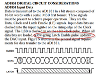
Latch Enable on pin 6 is indeed supposed to go low (inverse of the input you're seeing on pin 5) in order for U20 to do any useful work. http://www.analog.com/media/en/technical-documentation/data-sheets/AD1851_1861.pdf

Not seeing any reason why pin 6 of U24 should be stuck low when it's getting a clean latch of pin 5 - https://assets.nexperia.com/documents/data-sheet/74HC_HCT14.pdf - Think you may have honed in on the problem!

As to why this is happening... there are two options left:

1. U24 is FUBAR
2. Bad ground to U24(!) causing U24 to clamp the output signal to low

I'm out on site now with my head buried in a jukebox but when I get back I shall check and triple check that I'm on the right pins. Before I left I metered pin 6 of u24 to pin 6 of u20 and it's defiantly continuous so I believe I have read the schematic correct.
I was thinking while driving I should confirm voltages and grounds to u24 before I go considering it cracked. So I will do that too.
Do you believe that u20 should be ok and not pulling it to ground or would you recommend ordering both to be on the safe side?
 
Triple check that measurement - because if it's accurate then U24 looks very guilty indeed.

Latch Enable on pin 6 is indeed supposed to go low (inverse of the input you're seeing on pin 5) in order for U20 to do any useful work. http://www.analog.com/media/en/technical-documentation/data-sheets/AD1851_1861.pdf

Not seeing any reason why pin 6 of U24 should be stuck low when it's getting a clean latch of pin 5 - https://assets.nexperia.com/documents/data-sheet/74HC_HCT14.pdf - Think you may have honed in on the problem!

As to why this is happening... there are two options left:

1. U24 is FUBAR
2. Bad ground to U24(!) causing U24 to clamp the output signal to low
Nice work chaps getting there!!!
 
Do you believe that u20 should be ok and not pulling it to ground or would you recommend ordering both to be on the safe side?
At this point U20 could be fine, it could be broken in its own way - no way to tell until U24 is working and producing the correct output to Latch Enable pin U20, which right now it simply isn't. A malfunctioning latch signal would absolutely explain the noises. If you can temporarily make the output of U24 change by tapping it I'd call it confirmed as the source of all of the noises.

More than likely it's just a dead U24, or U24 is the circuit that's showing the most distress over grounds. U24 may be an IC but it's not a complex or expensive one. It's a 50p chip, so it's worth replacing it to rule it out.

With the cost of AD1581 chips I wouldn't order a replacement for that one at this time as it's a costly chip. It's entirely possible that U20 is pulling U24 down but that would be quite a catastrophic - and only periodic - failure within U20, whereas a crazed latch signal would produce the random noises, and the distorted but recognisable attempts at real noises.
 
Last edited:
Can I ask a question here chaps - on reading the dac datasheet unless I am wrong(and I may well be!!) the dac is expecting a low pulse to latch the dac , according to the datasheet extract below ????

upload_2018-1-4_14-20-6.png
 
Can I ask a question here chaps - on reading the dac datasheet unless I am wrong(and I may well be!!) the dac is expecting a low pulse to latch the dac , according to the datasheet extract below ????

View attachment 56773
Yep, which U24 as a 74HC14 chip has the simple job of inverting - except right now all it (seems) to be doing is flatlining it. The correct usually-low, pulsing-high signal is going into U24 and we should see the pulsing-low signal coming out
 
Back
Top Bottom