What's new
Pinball info

Register a free account today to become a member! Once signed in, you'll be able to participate on this site by adding your own topics and posts, as well as connect with other members through your own private inbox!

Expired Mod Power Expander Board for WPC and WPC-95 Games

Expired Due to no activity

myPinballs

Site Supporter
Joined
Nov 19, 2011
Messages
5,438
Location
Pudsey UK
Alias
Jim
As recently discussed on @chris b 's super minty tz restoration thread, i have developed a decent, cost effective way to power the rise of electronic mods for pinball without putting unnecessary load onto the ageing wpc driver board's 12v power circuit. The board is fed from a separate isolated 12v power supply rated at 5A max which can either be plugged in the games switched line input or separately, so no more driver board mod load issues. Also the board has power leds, fuse protection, and 5v output option. The output connectors follow the wpc layout standard. The fuse included with the board will be 4A.

Costs are as follows (all plus postage) :

£60 inc vat for the standard populated board with dedicated power supply. 12v output only
£80 inc vat for the fully populated board with dedicated power supply and both 5v and 12v output.

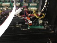
Some pics of the first assembled board, currently going through testing:

IMG_2702.JPG
fullsizeoutput_c92.jpeg
fullsizeoutput_c8e.jpeg


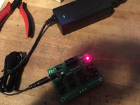
Testing the output load

fullsizeoutput_c90.jpeg
fullsizeoutput_c91.jpeg


If you'd like one for your wpc/wpc-95 game then please get in touch. I will build these in batches and will be on a first come first serve basis.

Cheers all
 

Attachments

  • fullsizeoutput_c8f.jpeg
    fullsizeoutput_c8f.jpeg
    111.1 KB · Views: 49
Last edited:
Jim,

Design alert... (From my perspective - apologies for the observations)... There's only one fuse, meaning that one Mod could take the entire board out. Plus this has effectively live pins exposed... would have made more sense (to me) to have female connectors to remove the risk of shorting..??

Cheers
Paul

Design alert? Yes 1 fuse for the output of the connectors, if there's a short the 5a power supply will shutdown anyway taking the board down on purpose so no need for more than 1 fuse. You hardly want to leave a shorted or badly wired device unchecked. The outputs are the same spec and design as the wpc driver board. Using female connectors would add complexity to the mod plugs and extra cost.
 
Simpleton head on.. I've got a load of mods on my TZ, but most if not all are crocodile clipped onto GI or Molex spliced nto original flasher or insert wiring. This wouldn't help with any of that stuff would it?

I have a TV mod which I know for sure is plugged into the power driver board via a Z-connector so that could go on there, but trying to work out what mods typically would run off this?
 
Looks good. You could put empty molex headers onto the unused pins to help prevent shorts too.
 
Looks good. You could put empty molex headers onto the unused pins to help prevent shorts too.

Thank you, some positive response is appreciated. Yeah i think that could be an option, though as mentioned the power supply is short protected anyway so would just shut down to protect everything. Shutting down completely from a single short is better in my mind rather than operating in a 'lets keep going' type approach. And yes before anyone pipes up i have tested the short scenario.
 
Simpleton head on.. I've got a load of mods on my TZ, but most if not all are crocodile clipped onto GI or Molex spliced nto original flasher or insert wiring. This wouldn't help with any of that stuff would it?

I have a TV mod which I know for sure is plugged into the power driver board via a Z-connector so that could go on there, but trying to work out what mods typically would run off this?

I'd have to see the mods in question, but for now just assume its the ones that are spliced off the power board (bottom left of wpc driver boards)
 
Apologies mate - as i said, it was just a personal observation - not meant as a negative...

Also from a personal perspective, I would rather a mod be taken out on it's own rather than taking everything on that board out. However, horses for courses :)
 
On the flip side, a dodgy mod would in the best case scenario blow the fuse on the WPC Power Driver Board, which could disable all sorts of stuff. At least a "mod board" blowing its fuse is only going to disable the mods that are connected to it, and allow you to keep on playing, rather than disabling stuff that's actually functional.

As a rule of thumb too it feels intuitively safer to plug things that are an unknown quantity into a board which could be ultimately sacrificial, rather than a 20+ year old circuit board that has to do so many other things, isn't the easiest thing to remove from the machine or fix, and of which there is a finite supply (I don't count Rottendog)
 
Apologies mate - as i said, it was just a personal observation - not meant as a negative...

Also from a personal perspective, I would rather a mod be taken out on it's own rather than taking everything on that board out. However, horses for courses :)

Put inline fuses on your mods then ;)

Saying that the board fuse would probably go before the mod one (unless lower rated I guess)
 
Last edited:
I find it pretty sad that there are silly negative comments on this and no positive ones I asked jim to build this board for me as I am doing a really nice tz with lots of mods and it’s a nice way to do it neatly and not to stress out the already struggling 12v on wide body games we didn’t have to make more for other people but he did
this board wasn’t thrown together overnight and Jim is well qualified to do it
As for the technical alert have you ever seen any pinball boards with fe male conectors on no
Bally stern and Williams boards have all been fine for many years running exposed male pins with voltage running through them at all times
And in most cases the mods fitted to games have fe male conectors so would have been pretty pointless putting these on the mod board
 
Hey Jim, pop me down for two, I don’t mind them in kit form - I’ll look forward to getting around to building them and popping one in my tz and taf, will look neater solutions than the current 12v transformers I put in myself.

Will pick them up when I’m able to but happy to pay for them as you need, also did you get into the problem with that RD board which had a power problem after 10-15min?
 
Chris,

Mine (which is where i am presuming that the above is pointed towards) aren't meant to be negative comments, they are a personal perspective, and a personal view of how things could be improved.
I am a great support of Jim's products, and would happily recommend his goods and services to others.

As for the technical alert have you ever seen any pinball boards with fe male conectors on no

Sorry Chris - Yes. The board that pinball life produces houses female connectors. I suspect exactly for that reason.

1540368784490.png


This isn't supposed to be a bitching thread... my fault i guess for putting my head above the parapet.
 
Chris,

Mine (which is where i am presuming that the above is pointed towards) aren't meant to be negative comments, they are a personal perspective, and a personal view of how things could be improved.
I am a great support of Jim's products, and would happily recommend his goods and services to others.


Sorry Chris - Yes. The board that pinball life produces houses female connectors. I suspect exactly for that reason.

View attachment 73383

This isn't supposed to be a bitching thread... my fault i guess for putting my head above the parapet.


Right, lets just leave this here. We are all friends. I've designed what i believe to be a decent board and you can have one should you wish. Or you can buy whatever other board you want, i'm not bothered. We just thought offering this as an option would be beneficial seeing as we'll be using them in high end restorations. As mentioned earlier though, these other boards are just splitters from the original power boards and don't really solve the overloading issue. Also the one you picture above is only rated at 2A for 12v which is because its plugged directly off one of the power boards 4 pin connectors.
 
I didn't read it as a negative comment either to be honest, just an observation. Perhaps one of those cases where the written word doesn't translate properly to intent.
 
Constructive criticism I believe the term is. Best to take it on board and learn from it we are all friends on this board.
 
I didn't read it as a negative comment either to be honest, just an observation. Perhaps one of those cases where the written word doesn't translate properly to intent.

When the comment is started by design alert then it’s not a good start maybe if it was brought up in a suggestion further in the post it may have been better if anyone can do a better job then knock your self out
Me and jim work hard to help the pinball community with shop logs and making new products I was going to carry on this post next week with it up and running in a heavily modified tz but I won’t be bothering now as my shop logs will also now end
This product will be available to buy on jims website if you want one
Or if you can do a better job of making one your self crack on
 
I was going to carry on this post next week with it up and running in a heavily modified tz
Actually @chris b , I for one would really like you to keep on with these, and in particular with this board in TZ. They are incredibly helpful, particularly for pinball idiots like me. I might be buying one shortly and would definitely be adding this board in if I do...
 
Actually @chris b , I for one would really like you to keep on with these, and in particular with this board in TZ. They are incredibly helpful, particularly for pinball idiots like me. I might be buying one shortly and would definitely be adding this board in if I do...
Same. I'm very much a noob when it comes to pinballs, so seeing how these things go from a bunch of bits into a restored machine is very interesting. I very much enjoy @chris b 's and other shop logs.

I've already expressed interest in buying Jim's mod, once I figure out what I will be running off it, and have already spoken to him about repairing a board (once I build up the courage to remove it). :thumbs:
 
I actually think this is a great idea.

But Jim, where does the 12v PSU plug into? Do you modify the AC outlet inside the game to work on the power switch (the one on the switch box)?

If this is bolted with stand offs under the playfield I personally do not see an issue having 12v and 5v 'live' pins being exposed. It also makes life easy for most of us who have the correct tool to do these molex connectors.

If you are only using a couple of mods then you can lower the fuse rating down to a 2a or 3a. It is a great idea to keep mods off your WPC/WPC95 boards.

Personally I would power a colordmd off one of these rather than the 5v/12v on the original PCB.

Yep you can power a colour dmd off here no problem. You have a few choices to power the supply. We’ll be using spare pins on the transformer line voltage plug, but you can wire to the power switch box switched side to or run externally. Of course caution should always be taken if wiring mains voltage cables
 
I won’t be bothering now as my shop logs will also now end

Please do not do that @chris b - your advice on this forum and showing us mortals the proper way to do things is greatly appreciated - has been a great help to me
 
Keen to buy one of these for my TAF.

The website says:
The board is fed from a separate isolated 12v power supply rated at 5A max which can either be plugged in the games switched line input or separately, so no more driver board mod load issues.
What does "the games switched line input" mean? Is this a port somewhere? Does it mean that if it uses the games switched line input that it is putting the load through the driver board as if the connectors were plugged into it?

Sorry for the noob questions but I'm not familiar with the terms.
 
Keen to buy one of these for my TAF.

The website says:

What does "the games switched line input" mean? Is this a port somewhere? Does it mean that if it uses the games switched line input that it is putting the load through the driver board as if the connectors were plugged into it?

Sorry for the noob questions but I'm not familiar with the terms.
I fitted one to my TZ best thing I’ve added... the plug on the mains transformer of your game it connect to the spare pins which are 240v so when you switch on your TAf so does your spare 12v board, I payed the extra for the 5v.

I’ve plugged my colour dmd into it as well plus my topper which needs 12v and 5v
 
Any chance of a photo of where it plugs into transformer? Not sure I understand where you mean.

Also where did you mount it?

Thanks.
 
Hope this helps
 

Attachments

  • 9CC040B0-7259-4768-A2AD-37F94B5296AA.jpeg
    9CC040B0-7259-4768-A2AD-37F94B5296AA.jpeg
    107.4 KB · Views: 70
  • A6D2FC9C-4AB2-48BF-9CF5-5FF4719C58E1.jpeg
    A6D2FC9C-4AB2-48BF-9CF5-5FF4719C58E1.jpeg
    84.8 KB · Views: 70
  • 8507149C-1C10-411F-AA23-9229D3A2AB81.jpeg
    8507149C-1C10-411F-AA23-9229D3A2AB81.jpeg
    124.3 KB · Views: 70
Thanks. It's kindof hard to see the wiring on my phone. Is what you received completely plug and play? You didn't have to splice wires or push them into connectors or anything like that?

Again sorry for the dumb questions but my electrical knowledge is next to non-existant.

Thanks
 
Back
Top Bottom