My BSD has been down, for a little while now. I'd put off looking at it because I was sure my multimeter was broken and giving me duff readings. So I borrowed a Fluke from @replicas, and now I'm pretty sure I have something very very wrong
All the test points on the driver board are out:
TP7, should be 20VDC, I see 7V
TP6, should be 50VDC, I see 7V
(Slightly weird maybe, but the 5VDC is pretty spot on, the game boots perfectly and I dare say I think it plays ok too apart from the 20VDC for the magnet motor being only 7V and so refusing to move)
So anyway, I went further back, to the incoming fuses F111 should be 16VAC I think. But I see 6VAC
F112 I think should be 16VAC too? But I see 27VAC?
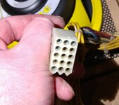
So then I went even further back, and (after some effort) yanked out the transformer output cable. First thing I noticed was that it looked like this:

And the voltages I get (all AC) are as follows. Anyone know how badly wrong this is?
(Assume I'm holding the connector upside down in that photo, then I see)
row 1 = RED , RED , WHITE/RED
= 10 , 4 , 11
row 2 = WHITE/RED , WHITE , GREY
= 3.5, 41, 23
row 3 = BLK/YEL , WHITE , GREY
= 40 , 36, 10
row 4 = BLK/YEL , WHT/GREEN , GREY
= 10 , 8 , 4
row 5 = WHT/GREEN , BLU/WHT , BLU/WHT
= 3, 13 , 6
I need a new transformer... right?
All the test points on the driver board are out:
TP7, should be 20VDC, I see 7V
TP6, should be 50VDC, I see 7V
(Slightly weird maybe, but the 5VDC is pretty spot on, the game boots perfectly and I dare say I think it plays ok too apart from the 20VDC for the magnet motor being only 7V and so refusing to move)
So anyway, I went further back, to the incoming fuses F111 should be 16VAC I think. But I see 6VAC
F112 I think should be 16VAC too? But I see 27VAC?
So then I went even further back, and (after some effort) yanked out the transformer output cable. First thing I noticed was that it looked like this:

And the voltages I get (all AC) are as follows. Anyone know how badly wrong this is?
(Assume I'm holding the connector upside down in that photo, then I see)
row 1 = RED , RED , WHITE/RED
= 10 , 4 , 11
row 2 = WHITE/RED , WHITE , GREY
= 3.5, 41, 23
row 3 = BLK/YEL , WHITE , GREY
= 40 , 36, 10
row 4 = BLK/YEL , WHT/GREEN , GREY
= 10 , 8 , 4
row 5 = WHT/GREEN , BLU/WHT , BLU/WHT
= 3, 13 , 6
I need a new transformer... right?

