What's new
Pinball info

Register a free account today to become a member! Once signed in, you'll be able to participate on this site by adding your own topics and posts, as well as connect with other members through your own private inbox!

Dr dude flipper and mixmaster issues

Hmmm, so...

The magnet coil does not work if the caps are removed from the flipper switches.
With the Magnet coil working the flippers stay up when pushed up manually.

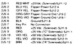
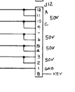
This implies to me that the magnet coil is grounded to the flipper ground either on the playfield or in the backbox. This could be a case of a wire has come out of one of the IDC plugs and been put back in the wrong place. First place I would check for this is Plug 5P12 that plugs into J12 on the Aux Power Board.

1
2 Grey / Yellow (flippers)
3
4 Blue / Yellow (flippers)
5
6 Violet / Yellow (Magnet coil and others)
7
8 KEY
9
10
11 Yellow / Violet (other coils)
12

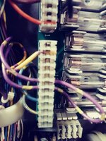
Ok. Thank you! I will check later today...

Also wanted to ask if that doesn't work does anyone know if a Funhouse board would work in this? I have a Funhouse machine I could swap boards out with to try to diagnose...
 
Hmmm, so...

The magnet coil does not work if the caps are removed from the flipper switches.
With the Magnet coil working the flippers stay up when pushed up manually.

This implies to me that the magnet coil is grounded to the flipper ground either on the playfield or in the backbox. This could be a case of a wire has come out of one of the IDC plugs and been put back in the wrong place. First place I would check for this is Plug 5P12 that plugs into J12 on the Aux Power Board.

1
2 Grey / Yellow (flippers)
3
4 Blue / Yellow (flippers)
5
6 Violet / Yellow (Magnet coil and others)
7
8 KEY
9
10
11 Yellow / Violet (other coils)
12


Ok. All looks good except the violet/yellow wire goes through 6 and 7. Not just 60519181714_Film1.jpg
 
Dang,
The pins are doubled up so the loop is fine...
Screen Shot 2018-05-20 at 12.16.13.png

Well if it was me the next thing I would be doing is testing continuity on all the plugs from the playfield and I would do each pin the each other pin and then repeat with the probes round the other way. Its a pain in the ass but its the only way of knowing for sure if there is a short on the playfield somewhere.

I have a feeling this may be one of those things you live with and then when the mood takes you a little more hunting is done until one day a fix so obvious is found that we all wonder how we missed it in the first place.
 
Dang,
The pins are doubled up so the loop is fine...
View attachment 65244

Well if it was me the next thing I would be doing is testing continuity on all the plugs from the playfield and I would do each pin the each other pin and then repeat with the probes round the other way. Its a pain in the ass but its the only way of knowing for sure if there is a short on the playfield somewhere.

I have a feeling this may be one of those things you live with and then when the mood takes you a little more hunting is done until one day a fix so obvious is found that we all wonder how we missed it in the first place.

Thanks again for all your help
You mean just put probes on each prong of a plug? Or from the plugs to somewhere else? Because I did get continuity between the wires on the coil and wires on the magnet when everything was plugged in. I was told to unplug the magnet from the backbox and then I didn't get continuity
 
It is test of will and it may give you zero answers but I would test each of these plug terminals on the wires harness against all the others.

I would start from one end and work my way to the other and probably spend an hour doing it but if you want to try and do it in a targeted approach try starting with all of the contacts on the plugs that go into 2J5, and 2J8.
Screen Shot 2018-05-20 at 16.12.37.png Screen Shot 2018-05-20 at 16.11.35.png
Take pin 1 and test against 2,3,4,5...yada yada, if you get a buzz make a note and keep going until all pins are tested against each other. Hopefully something will be wrong and the answer will be on the playfield.
 
Last edited:
One other thing I tried today was reading volts at the flipper coil
I read this today with a voltmeter with leads on the coil for The Flipper it reads 65 volts then when I hit the Target and operate the magnet it drops to 45 v ...(if I hold the flipper button in) and if I leave go of The Flipper button at the same time I operate the magnet it drops to about 3.7 volts and holds til the magnet releases then goes to 0
 
Yeah, that shows the flipper coils are defo grounded somewhere and via something with a big resistance.
I attached the wrong image on my previous post, now fixed.
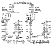
The flipper circuit from the schematics attached here as well as the flipper power circuit. we can see +50v comes in at the top and flows down, as the flippers are still
grounded regardless of the flipper buttons the fault must be (in my mind) before or at connection 2J10.
Screen Shot 2018-05-20 at 12.42.33.png


Screen Shot 2018-05-20 at 20.03.12.png
 
Does Dr Dude have lane change ? If it does are the EOS switched wired up correctly and are the two sets of switched on each flipper correctly insulated from each other ?
 
One last thing... The White / Violet wire going to the GI lamp in this pic of yours (from by the magnet coil). Its not touching the coil is it ?
I have a voice in the back of my head asking why the flipper button would make a light flash as you described earlier.
Screen Shot 2018-05-20 at 20.54.29.png
 

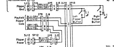
Your photo of the double looped wire shows that you are missing an earth wire to pin 1 (also called GND). Assuming the circuit diagram is correct then I think this needs replacing before any further fault finding.

The circuit diagram of the flipper set-up shows lane switch change for the left and right flipper buttons - the right side with GRN-GRY and WHT-BRN wires attached to the switch.

One last thing... The White / Violet wire going to the GI lamp in this pic of yours (from by the magnet coil). Its not touching the coil is it ?
I have a voice in the back of my head asking why the flipper button would make a light flash as you described earlier.

I would be very surprised that it is touching as the coil voltages would destroy the lighting circuit.
 
Last edited:
I would replace the .1uF 500V capacitor on the right flipper button, it sounds like it might be shorting out. You have said when you remove it the magnet doesn't activate and that when you hold the flipper up manually it engages and holds tell me that there is power in the circuit even when the flipper button is not being pressed. The capacitor one route for the power to bypass the flipper button and needs to be ruled out.
 
I would replace the .1uF 500V capacitor on the right flipper button, it sounds like it might be shorting out. You have said when you remove it the magnet doesn't activate and that when you hold the flipper up manually it engages and holds tell me that there is power in the circuit even when the flipper button is not being pressed. The capacitor one route for the power to bypass the flipper button and needs to be ruled out.
Ok
Ill order some and change it
Thanks very much
 
I would replace the .1uF 500V capacitor on the right flipper button, it sounds like it might be shorting out. You have said when you remove it the magnet doesn't activate and that when you hold the flipper up manually it engages and holds tell me that there is power in the circuit even when the flipper button is not being pressed. The capacitor one route for the power to bypass the flipper button and needs to be ruled out.

Would these work? They look much different.
https://rover.ebay.com/rover/0/0/0?mpre=https://www.ebay.com/ulk/itm/381844850122
 
I would replace the .1uF 500V capacitor on the right flipper button, it sounds like it might be shorting out. You have said when you remove it the magnet doesn't activate and that when you hold the flipper up manually it engages and holds tell me that there is power in the circuit even when the flipper button is not being pressed. The capacitor one route for the power to bypass the flipper button and needs to be ruled out.

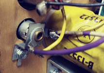
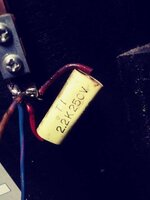
Ok. Is this what you meant? Cause they look like this..it has different numbers15271114638581721246895.jpg
 
Yes, it looks like a totally wrong part fitted, possibly an operator bodge to keep the game running at the time.
 
Remove the switch capacitor and retest. The capacitor is only there to suppress the sparking contacts and extend its life. If the problem goes away without the capacitor then replace the capacitor a with the correct part and job done.
 
Clutching at straws here: There is a capacitor across each flipper button switch. There is a slim, slim chance that those could be part of the problem - I doubt it, but I would remove them temporarily just to rule them out.

This issue has really got me intrigued, I must say!
Well, I did desolder the capacitors on The Flipper buttons and at first I thought it worked and was really excited because the flippers weren't staying up anymore but then I noticed the magnet wasn't actually engaging when I threw a ball at the Target instead of just hitting it with my fingers. So I put the capacitors back on and the magnet is now working but the problem has come back. Also wanted to say the flippers will actually stay up if I just manually put them up with my hand not just hit the button. They don't seem to be holding as strong if I just lift them up with my hand though if that makes any sense[/QUOTE]
 
Take the capacitors off. Proceed to work out why the magnet isn’t working.

I suspect you have two problems, the capacitors and some other wiring fault


The capacitors should not affect the magnet but they do. So take them out of the equation until you’ve got the magnet to work. Putting them back on to get the magnet to work is hiding the underlying problem.

With caps removed go back to measuring the voltage at the magnet. If absent find out why.
 
Where are you located ? Perhaps someone can visit with a fresh pair of eyes might spot something.
 
Take the capacitors off. Proceed to work out why the magnet isn’t working.

I suspect you have two problems, the capacitors and some other wiring fault


The capacitors should not affect the magnet but they do. So take them out of the equation until you’ve got the magnet to work. Putting them back on to get the magnet to work is hiding the underlying problem.

With caps removed go back to measuring the voltage at the magnet. If absent find out why.

I'll try this later today or at least over the weekend
 
Did you get this issue resolved? I was just reading so intrigued as to what the fault was...
No...I got frustrated because I can't figure it out. Was thinking of selling the game because with my OCD its hard for me to play a game knowing there is something not right with it..
 
Back
Top Bottom