What's new
Pinball info

Register a free account today to become a member! Once signed in, you'll be able to participate on this site by adding your own topics and posts, as well as connect with other members through your own private inbox!

In Progress Bram stokers shop log and mods

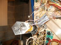
@RudeDogg1 If you recall I did something similar with my WH20 - right coils in right places, but some of the coils have 3 wires on - one is effectively the signal going to ground, and the other two are the 50v feed. I accidentally paired a ground with the a 50v supply on one side of the coil, and the other 50v one to the other side of the coil. This had weird effects. both 50v should be on one lug the and the signal on the other. Check it out it may help.

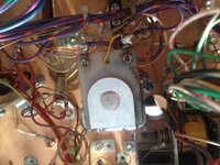
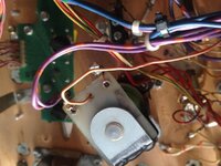
Here is a pic on one I screwed up - the 2 thick purple/yellows should be on one lug and the thin(signal) brown on the other.(so photo show them wrong!!)

Hope this helps

Cheers Kev

P4170014.JPG

CHeers Kev
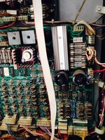
 
Rudi get some pics of the coil's wiring you've had off up, plenty of dracs out here to compare.
 
Sorted em now I just went by the solenoid test and swapped the culprits over. Just got a couple switch issues and the tiny cool for the left wire gate isn't firing for some reason
 
Just in case anybody gets stuck in a similar situation in the future then refer to the game manual. The wire colours for each coil are listed in the solenoid charts. :thumbs:
 
I've tried to get a pic of the light mods they don't pick up very well on an iPhone sadly but you get the idea

It doesn't pick up the flicker very well


If any of you decide to get the light mods from me with the village I'd suggest you don't have ott LEDs under it like on mine it will drown them out. Will get a better vid in game tomoz I've given up for the night
 
Right people this thing is really pishing me off so I need some help before I burn it or admit defeat and call Neil f out. I'd rather sort it out my self as I'm sure it's an easy fix.

I've now swapped the pop bumper coils twice and it's still doing the same (I did it a second time thinking I'd just put them back the same).

Basically in solenoid test the bottom pop is the ramp down and in switch test. Left pop is the bottom one also in switch test.

Also think there is a column out because switch on the small ramp, optos on the big ramp (next to asylum), asylum up kicker optos, small left gate coil and both right sling switches don't work.

I've no idea where to start and I don't really understand the weird grid schematics much prefer the old type.

There is 1 2 pin connector (grn wht) not connected that I can't find where it connects. Earlier today I found what I think is the other half on the floor but can't for the life of me see what it's off. I'd really like to get this sorted before Xmas so I can clear me **** up and get on with my painting that people are waiting on
 
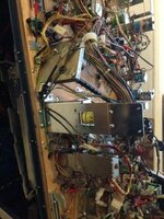
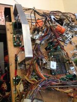
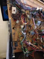
Rudi can you send detailed underside playfield pics ins sections so I can take a look and perhaps compare ? might find the fault straight away that way - try an make sure all connectors and coil connections are visible?

It does sound like a very similar fault I had on my WH20 when I shopped it ????

Cheers Kev
 
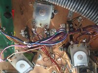
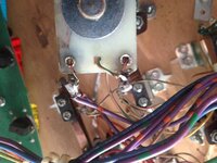
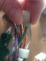
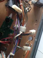
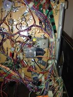
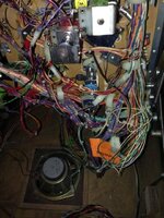
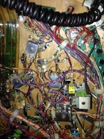
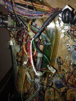
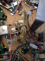
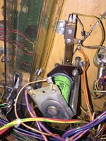
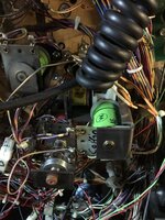
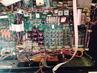
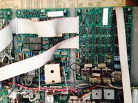
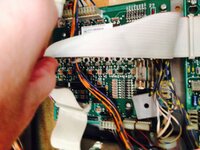
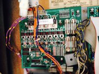
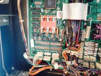
Hi Rudi heres some close ups of the pop bumpers and the green and white 2 pin connectors hope they help. If you need anymore let me know

Good luck ;)image.jpegimage.jpegimage.jpegimage.jpegimage.jpegimage.jpegimage.jpegimage.jpeg
 
Haven't you got one of the pop bumper's coils mixed up with the coffin ramp coil? The doubled up wires on my pop bumpers are all violet/orange, whereas the coffin ramp coil is violet/yellow.

image.jpeg image.jpeg
 
Last edited:
Just the coils muddled like I'd first diagnosed I never actually disconnected any wires on any of the machine other than the eos switches and sling switches. Some how despite labelling the coils when I kept moving them around they were still the wrong order twice lol. Just need to get my head around the other probs which I'm sure it's a column or 2 out
 
Well I've got abit further the mystery connector was off the movie ramp mech so that's sorted.

So the remaining problems are:

The optos in the left side of the plastic ramp arnt working.

The score switch on the small plastic ramp ain't working.

Outer left drain switch ain't working.

Left wire gate mini coil isn't working.

Both right sling switches arnt working.

Even tho it works it's saying there is an up ramp error.

Both left popper optos work but they seem to keep firing every 10 seconds or so and it says one of them has an error

 
Been investigating the left gate coil. It's got continuity from the 2 main connectors . It's getting 70v on the top tab (violet) and barely half a volt on the lower tab. No idea what it should be but thought that may be a help if any experts chime in. What readings should I get from the corisponding tip 102 (U7)?
 
Well I thought I'd got somewhere then yours is connected at J208 where as mine was J209 but swapping them made no difference at all sighs
 
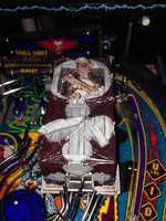
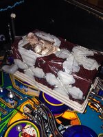
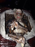
I used transparent paint for the soil, eyes and cracks in the planks. Here's a quick vid with the flashers going. With this mod it just slips over the existing coffin plinth once you remove Ron you also remove the tombstone with the lock lights and the light board. There is a light mod in the form of gothic torches on the works to replace the lock ones.

 
Rudi you've an obvious talent for art it looks fantastic, he's certainly a little more scary than my Ron or should I call him Wagner who's about to break out into a rendition of 'she bangs' :rofl:

Top job :clap:
 
Been investigating my problems fixed the left ramp score switch it had a break under the shrink tubing on the male connector side so replaced the wires.

So been investigating the bottom left popper (switch 55) on single switch test its saying open and when u break the beam it does nothing. In switch edge test it works. So then I unplugged the connector and plugged it into the next pair and now that one says open. So it's something on that connectors side no idea what tho.

Also investigated the left ramp optos (switch 73) which arnt working. Has continuity from optos to the connector. Connected it to a connector for the optos on the other side and it works fine. So I measured the voltage from the connector and it's the same as the working side. Is this board issues? Still a few rows or columns of lights out to

Any ideas guys?
 
Me neither :rofl:

I think they control the optos. Small surface mounted chip on the opto board. My pinballs was selling them a while back.
 
Back
Top Bottom